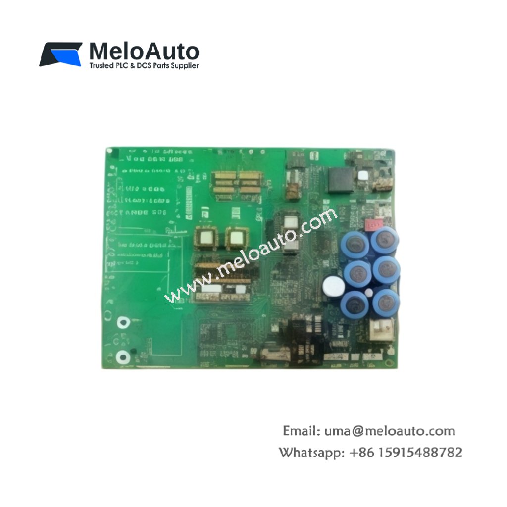
This GE DS200EXPSG1A DS200EXPSG1ACB Power Supply Board provides regulated DC power for EX2000 excitation systems. The board accepts a wide input range from 85V to 265V AC or DC. You will find this component in many industrial generator control cabinets. The DS200EXPSG1ACB variant includes a rugged conformal coating for harsh environments.
Technical Specifications
| Parameter | Specification |
|---|---|
| Full Model | GE DS200EXPSG1A DS200EXPSG1ACB Power Supply Board |
| Category | Power Supply Board |
| Input Voltage | 85V to 265V AC (47-63 Hz) or 100V to 300V DC |
| Output Voltages | +5V, +15V, -15V, +24V |
| Output Current | 10A (+5V), 4A (+15V), 2A (-15V), 3A (+24V) |
| Efficiency | 88% Typical at Full Load |
| Hold-Up Time | 20 ms at Full Load |
| Dimensions (H x W) | 250 mm x 140 mm |
| Weight | Approximately 1.10 kg |
| Connectors | 2 x Terminal Blocks, 1 x 20-Pin Header |
| Component Count | 192 Discrete Components |
| Energy Storage | 4 x 1500 µF Bulk Capacitors |
Power Conversion and Regulation Features
The GE DS200EXPSG1A DS200EXPSG1ACB Power Supply Board uses a flyback converter topology. This design provides excellent line regulation across the entire input range. Each output has independent overcurrent protection with automatic recovery. Furthermore, the board includes overvoltage protection on all output rails. Consequently, downstream cards receive clean, stable power continuously.
Installation and Connection Steps
Mount this GE DS200EXPSG1A DS200EXPSG1ACB Power Supply Board in any EX2000 cabinet slot. First, connect the AC or DC input to the TB1 terminals. After that, attach your load devices to the output terminals on TB2. Then, secure the board using four M4 mounting screws at the corners. Finally, verify each output voltage before connecting sensitive field circuits.
Energy Discharge and Safety Notice
This GE DS200EXPSG1A DS200EXPSG1ACB Power Supply Board stores significant energy in its capacitors. Therefore, you must wait at least three minutes after power removal. The four bulk capacitors discharge through internal bleeder resistors. Never short the output terminals to discharge the board faster.
Status Indication and Diagnostics
Four green LEDs show the presence of each output voltage clearly. A yellow LED indicates the board is in normal operating mode. A red fault LED illuminates when any output falls below 90% of nominal. These indicators help technicians diagnose power issues without any test equipment.


WeChat
Scan the QR Code with wechat