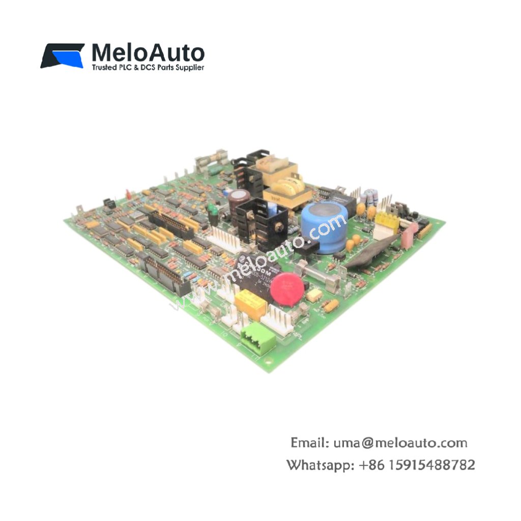
Technical Overview of the GE DS200SBCAG1A DS200SBCAG1AFC Drive Board
This GE DS200SBCAG1A DS200SBCAG1AFC Drive Board provides gate drive signals for power semiconductor devices. The board receives low-voltage PWM commands and amplifies them for SCR or IGBT gates. You will find this component in many GE Mark V excitation and drive systems. The DS200SBCAG1AFC variant includes a rugged conformal coating for harsh environments.
Technical Specifications
| Parameter | Specification |
|---|---|
| Full Model | GE DS200SBCAG1A DS200SBCAG1AFC Drive Board |
| Category | Drive Board |
| Number of Channels | 6 Independent Gate Drivers |
| Input Logic | 5V or 15V PWM (Opto-Isolated) |
| Output Voltage | +15V / -8V for IGBT Gates |
| Peak Output Current | 5 A per Channel |
| Isolation Voltage | 2500 V RMS (Input to Output) |
| Switching Frequency | Up to 20 kHz |
| Dimensions (H x W) | 220 mm x 130 mm |
| Weight | Approximately 0.72 kg |
| Connectors | 2 x 20-Pin Headers, 6 x Gate Output Terminals |
| Component Count | 168 Discrete Components |
| Energy Storage | 6 x 10 µF Gate Charge Capacitors |
Gate Drive and Protection Features
The GE DS200SBCAG1A DS200SBCAG1AFC Drive Board amplifies PWM signals for reliable power device switching. Each channel includes desaturation detection for short circuit protection. The board also provides active clamping to prevent overvoltage during turn-off. Furthermore, it monitors gate voltage and reports faults back to the controller. Consequently, your power stack receives clean, protected gate signals continuously.
Installation and Connection Steps
Mount this GE DS200SBCAG1A DS200SBCAG1AFC Drive Board near the power stack in the drive cabinet. First, connect the PWM input cables to the two 20-pin headers. After that, wire each gate output to the corresponding power device gate terminal. Then, connect the emitter or source sense leads for desaturation monitoring. Finally, verify each gate waveform using an oscilloscope before enabling DC power.
Energy Discharge and Safety Notice
This GE DS200SBCAG1A DS200SBCAG1AFC Drive Board stores minimal energy in its gate capacitors. However, you must wait 30 seconds after power removal before handling. The six capacitors discharge through internal bleeder resistors. Never disconnect gate wiring while the board remains powered.
Status Indication and Diagnostics
Six green LEDs show active gate drive signals for each channel. A red LED illuminates when any channel detects a desaturation fault. A yellow LED flashes during normal PWM signal reception. These indicators help technicians troubleshoot drive issues without an oscilloscope.


")


 Analog I/O Module")


WeChat
Scan the QR Code with wechat