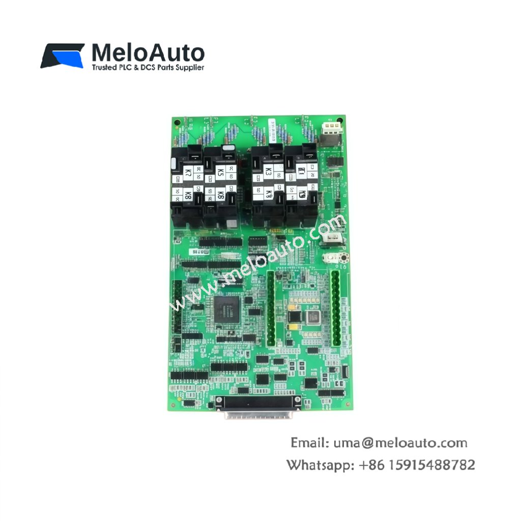
This GE DS200VPBLG1A DS200VPBLG1AFF VME Board serves as a backplane interface for Mark V rack systems. The board provides power and signal distribution to all VME cards in the chassis. You will find this component in many GE turbine control cabinets worldwide. The DS200VPBLG1AFF variant includes an extended temperature range for harsh environments.
Technical Specifications
| Parameter | Specification |
|---|---|
| Full Model | GE DS200VPBLG1A DS200VPBLG1AFF VME Board |
| Category | VME Board |
| Backplane Slots | 12 VME Card Positions |
| Bus Architecture | VME64 (A24/D16/D32) |
| Power Distribution | +5V, +12V, -12V, +24V Rails |
| Maximum Current | 30 A Total across All Rails |
| Signal Layers | 6-Layer PCB with Ground Planes |
| Dimensions (H x W) | 6U x 160 mm (Standard) |
| Weight | Approximately 1.85 kg |
| Connectors | 12 x P1/P2 Backplane, 2 x Power Inputs |
| Component Count | 42 Passive Components (Termination) |
| Energy Storage | 8 x 100 µF Decoupling Capacitors |
Backplane and Signal Routing Features
The GE DS200VPBLG1A DS200VPBLG1AFF VME Board distributes power and signals to all twelve rack slots. Each slot has independent power filtering for noise reduction. The board includes active bus termination to prevent signal reflections. Furthermore, it provides diagnostic access to all VME bus lines. Consequently, you can troubleshoot communication issues from a single point.
Installation and Connection Steps
Mount this GE DS200VPBLG1A DS200VPBLG1AFF VME Board as the backplane inside any Mark V rack chassis. First, secure the board using the factory-installed standoffs. After that, insert each VME card into its designated slot carefully. Then, connect the main power supply cables to the power input connectors. Finally, verify all slot guides align properly before powering up the system.
Energy Discharge and Safety Notice
This GE DS200VPBLG1A DS200VPBLG1AFF VME Board stores minimal energy in its decoupling capacitors. However, you must wait 30 seconds after power removal before handling. The eight capacitors discharge through internal bleeder resistors. Never insert or remove cards while the backplane remains powered.
Status Indication and Diagnostics
A green LED indicates the presence of valid backplane power. A red LED illuminates when any power rail falls below specifications. Four additional LEDs show the status of individual voltage rails. These indicators help technicians verify power distribution without removing any cards.


 Analog I/O Module")


WeChat
Scan the QR Code with wechat