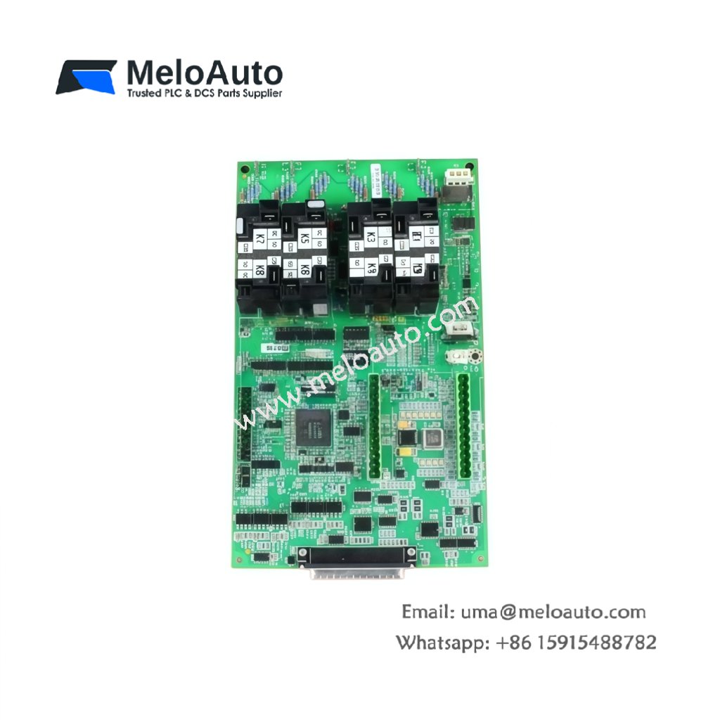
This GE DS200FCGDH1B DS200FCGDH1BCA Control PLC Module executes real-time control logic for Mark V turbine systems. The module processes analog and digital inputs to determine output states. You will find this component in many GE power generation applications worldwide. The DS200FCGDH1BCA variant includes a conformal coating for moisture-prone environments.
Technical Specifications
| Parameter | Specification |
|---|---|
| Full Model | GE DS200FCGDH1B DS200FCGDH1BCA Control PLC Module |
| Category | Control PLC Module |
| Processor | 32-Bit RISC at 66 MHz |
| Program Memory | 1 MB Flash (User Logic) |
| Data Memory | 512 KB RAM |
| Scan Rate | 1 ms per 1K Logic Steps |
| I/O Capacity | 256 Digital, 64 Analog |
| Communication | ARCNET, RS-232, RS-485 |
| Dimensions (H x W) | 230 mm x 160 mm |
| Weight | Approximately 1.15 kg |
| Connectors | 2 x 50-Pin Headers, 3 x Serial Ports |
| Component Count | 386 Discrete Components |
| Energy Storage | 8 x 100 µF Decoupling Capacitors |
Processing and Control Features
The GE DS200FCGDH1B DS200FCGDH1BCA Control PLC Module executes user-defined control logic deterministically. A real-time operating system ensures consistent scan timing for all tasks. The module supports ladder logic, function block, and structured text programming. Furthermore, it includes battery-backed memory for data retention during power loss. Consequently, critical setpoints and counters survive system shutdowns.
Installation and Connection Steps
Mount this GE DS200FCGDH1B DS200FCGDH1BCA Control PLC Module in any Mark V rack slot. First, connect I/O cables to the two 50-pin headers securely. After that, attach serial communication cables to the RS-232 or RS-485 ports. Then, insert the module fully into the backplane connectors. Finally, apply power and verify the boot sequence completes without errors.
Energy Discharge and Safety Notice
This GE DS200FCGDH1B DS200FCGDH1BCA Control PLC Module stores minimal energy in its capacitors. However, you must wait 30 seconds after power removal before handling. The eight decoupling capacitors discharge through internal resistors. Never remove the battery while the module remains powered.
Status Indication and Diagnostics
A green LED indicates the processor is running normally. A yellow LED flashes during active communication on the ARCNET bus. A red LED illuminates when a program fault or watchdog timeout occurs. Two additional LEDs show serial port activity for troubleshooting.


 Analog I/O Module")


WeChat
Scan the QR Code with wechat