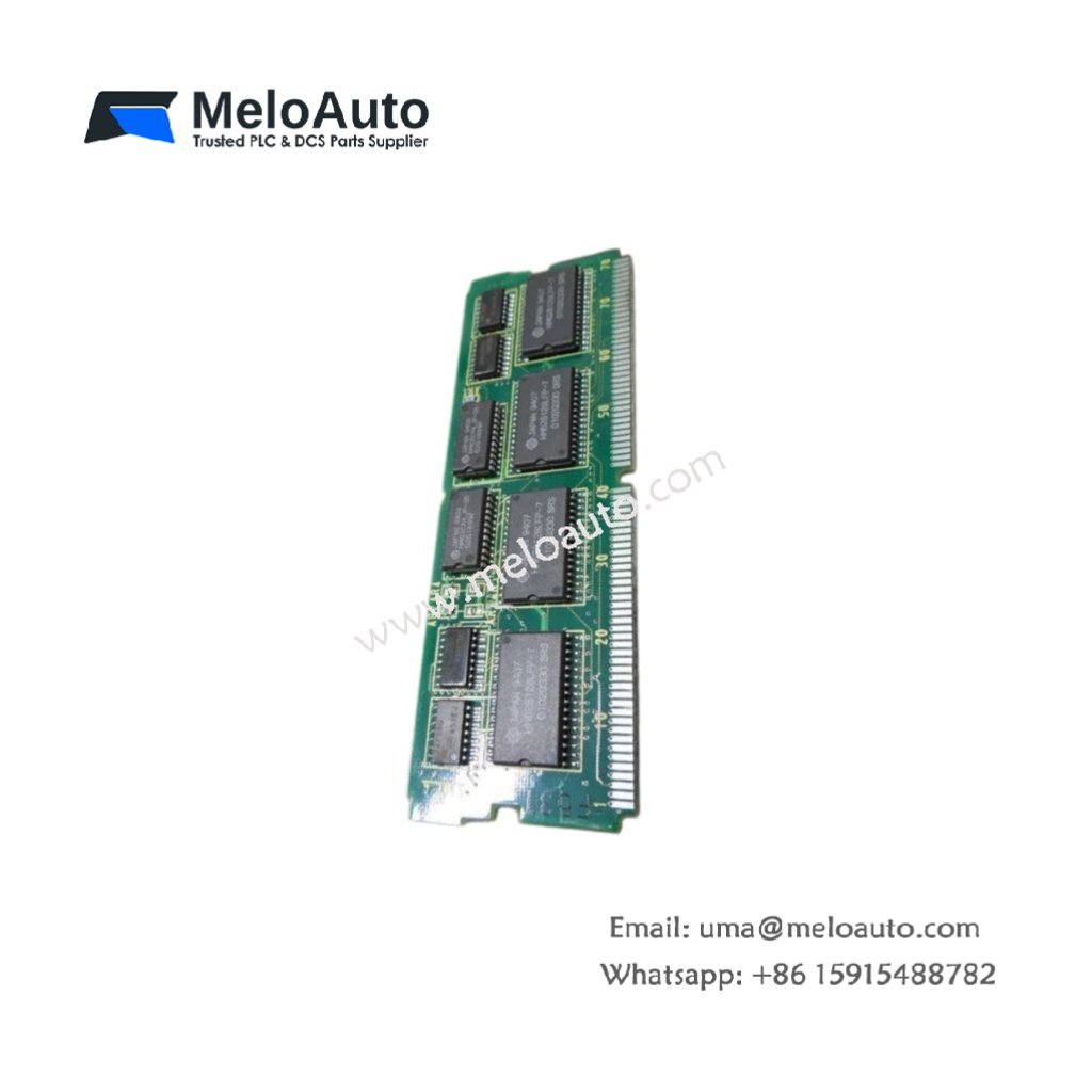
This circuit board serves as a control interface for GE Fanuc CNC systems. The GE A20B-2900-0500/04B handles signal processing and communication between system components. It measures 250 mm in width and 200 mm in height. This unit weighs approximately 0.48 kg for cabinet mounting.
Technical Specifications Table
| Parameter | Value |
|---|---|
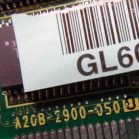
| Product Model | GE A20B-2900-0500/04B |
| Brand | GE Fanuc |
| Category | Circuit Board Module / CNC Interface |
| Compatible Series | GE Fanuc CNC Systems |
| PCB Layers | 6-layer circuit board |
| Surface Finish | Gold-plated pads and connectors |
| Dimensions (W x H x D) | 250 mm x 200 mm x 15 mm |
| Weight | 0.48 kg |
| Connector Types | 3 x 20-pin headers, 2 x ribbon cable ports |
| Internal Components | 1 x main processor, 4 x memory chips, 2 x driver ICs |
| Memory Type | Flash ROM (256 KB) + SRAM (128 KB) |
| Energy Storage | 1 x 0.1 F super capacitor (data retention: 48 hours) |
| Digital I/O | 16 channels (configurable) |
| Clock Speed | 16 MHz |
| Operating Voltage | 5 V DC and 24 V DC |
| Power Consumption | 250 mA at 5 V, 100 mA at 24 V |
| LED Indicators | 3 x status (Power, Run, Fault) |
| Operating Temperature | 0°C to 55°C |
Internal Design and Processing Architecture
This circuit board uses a 6-layer PCB with gold-plated contact pads. A main processor runs at 16 MHz for real-time control tasks. The GE A20B-2900-0500/04B stores firmware in flash ROM for field updates. SRAM provides temporary data storage during normal operation. A super capacitor retains critical configuration data for 48 hours without power. Consequently, this board maintains settings during short maintenance shutdowns.
Installation and Configuration Guide
First, mount this circuit board onto standoffs inside your CNC cabinet. Next, connect the ribbon cables to matching headers on adjacent boards. Then, connect 5 V DC and 24 V DC power supplies to the designated terminals. Verify all connector orientations before applying power to the board. The module automatically initializes when you power up the system. Three LED indicators show power, run status, and fault conditions. This circuit board works with GE Fanuc CNC systems and compatible interface modules. Always use a grounded ESD strap when handling this board to prevent static damage.


 Analog I/O Module")


WeChat
Scan the QR Code with wechat