 MeloAuto-Trusted PLC & DCS Parts Supplier
Key Features and Input Architecture
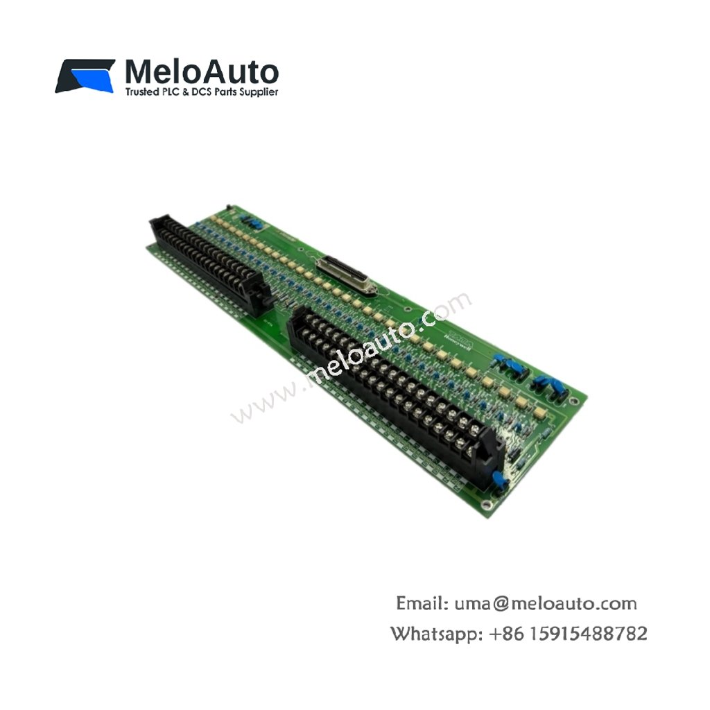
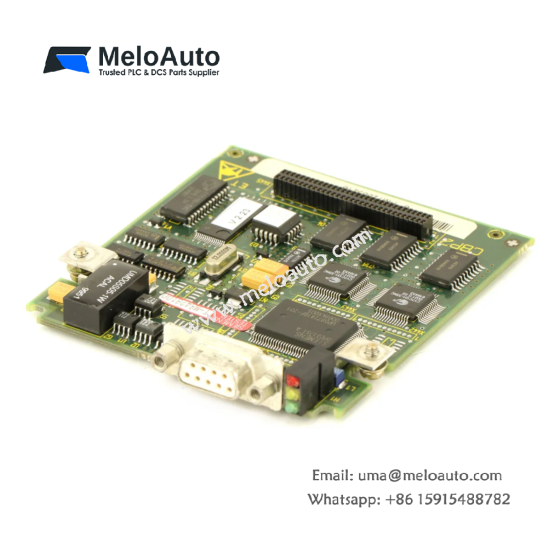
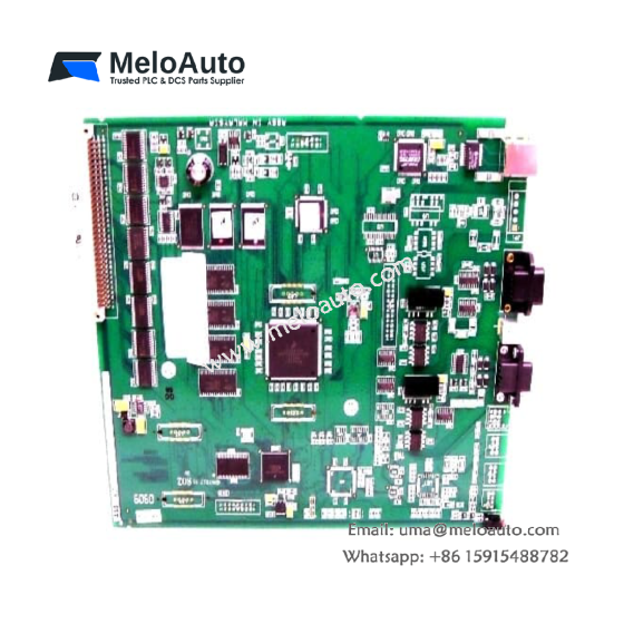
This digital input board provides 24 VDC signal acquisition for demanding process applications. It integrates sixteen isolated channels for direct field device connectivity. Each channel includes individual optical isolation to eliminate ground loop interference. The board also features built-in surge suppression for transient overvoltage protection. Field indicators display per-point status and module health simultaneously.
Technical Specifications
| Parameter | Specification |
|---|---|
| Model Number | MU-TDID72 51303928-100 |
| Input Channels | 16 isolated digital inputs |
| Nominal Voltage | 24 VDC |
| Input Range | 18–32 VDC |
| On-State Threshold | >15 VDC |
| Off-State Threshold | <5 VDC |
| Input Impedance | 3.6 kΩ typical |
| Isolation Voltage | 1500 VAC (channel-to-backplane) |
| Surge Protection | 1.5 kV transient suppression |
| Current Draw | 150 mA typical at 24 VDC |
| Power Loss | 4.0 W maximum |
| Operating Temperature | 0°C to +60°C |
| Storage Temperature | –40°C to +85°C |
| Dimensions | 130 mm x 32 mm x 140 mm |
| Unit Weight | 0.38 kg |
| Field Termination | 50-pin D-sub connector |
| Status LEDs | 16 individual channel indicators plus power LED |
Signal Processing and Response
This board captures input state changes with a typical response time under 1 ms. Each channel operates independently without affecting neighboring inputs. The module also includes a programmable debounce filter to suppress contact bounce. This feature eliminates false triggers from mechanical switch operations. The filter time adjusts through system configuration software for flexible tuning.
Wiring and Connector Details
The MU-TDID72 terminates field wiring through a high-density 50-pin D-sub connector. Use a mating cable assembly with appropriate gauge wiring for reliable connections. The board supports both sinking (NPN) and sourcing (PNP) field devices. Arrange wiring systematically to simplify future troubleshooting efforts. Secure all connections firmly to prevent intermittent signal loss.
Power and Energy Characteristics
Internal circuitry stores sufficient charge to bridge brief power dips up to 10 ms. This board draws 150 mA from the system backplane under normal operation. Total heat dissipation reaches 4.0 W at maximum load. Proper ventilation ensures stable thermal performance within the specified range.
Installation Guidelines
Insert the board carefully into an available Series T I/O slot. Lock the ejector tabs to secure the board firmly in position. Tighten the two retaining screws on top and bottom for mechanical stability. Connect the field wiring harness before applying system power. Verify LED patterns after startup to confirm normal operation.
Environmental Tolerance
This board operates reliably in temperatures from 0°C to 60°C. It withstands humidity levels ranging from 5% to 95% non-condensing. A protective conformal coating shields the PCB from contaminants. This robust design suits chemical plants, refineries, and power generation facilities.
Diagnostics and Maintenance
Front-panel LEDs immediately indicate each channel’s on/off condition. The system software retrieves detailed diagnostic data through the backplane. Replace the board promptly if multiple channels show inconsistent behavior. Perform routine visual inspections of connectors and wiring terminations.




WeChat
Scan the QR Code with wechat