 MeloAuto-Trusted PLC & DCS Parts Supplier
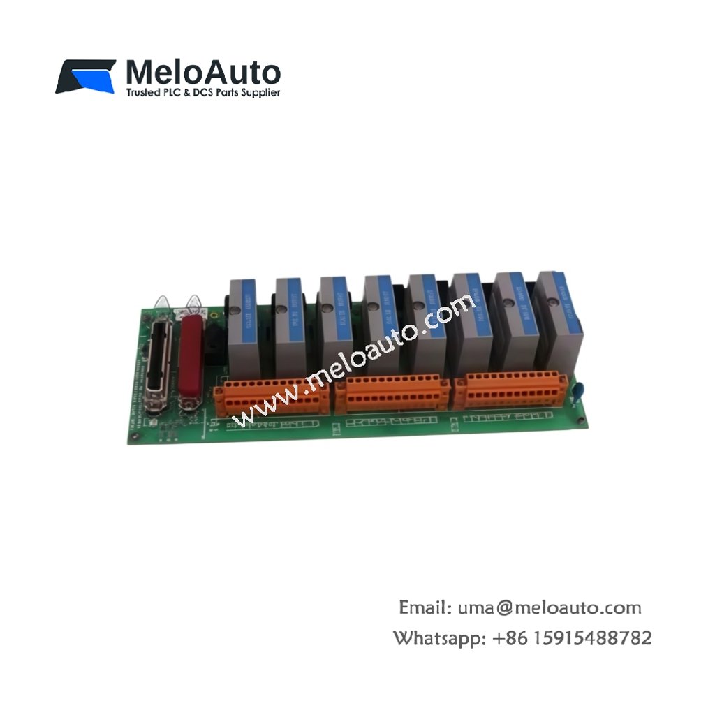
Termination Interface and Channel Configuration
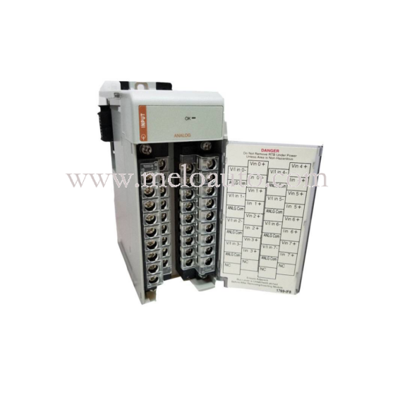
This termination board serves as the primary field wiring interface for analog input signals. It supports up to twelve differential or single-ended analog channels in a compact form factor. Each channel accommodates standard 4–20 mA current loops or 1–5 VDC voltage inputs. The board also provides dedicated terminals for each channel’s positive and negative leads. This design simplifies wiring organization and reduces installation errors significantly.
Technical Specifications
| Parameter | Specification |
|---|---|
| Model Number | MC-TAIL12 |
| Channel Count | 12 analog input terminations |
| Signal Types | 4–20 mA or 1–5 VDC (configurable) |
| Termination Style | Screw-type terminal blocks |
| Wire Gauge Range | 14–22 AWG |
| Common Mode Voltage | ±10 VDC maximum |
| Channel Isolation | Non-isolated (relies on input module) |
| Current Burden | 250 Ω typical (4–20 mA mode) |
| Input Impedance (Voltage) | 10 MΩ minimum |
| Operating Temperature | 0°C to +60°C |
| Storage Temperature | –40°C to +85°C |
| Dimensions (H x W x D) | 130 mm x 210 mm x 25 mm |
| Weight | Approximately 0.45 kg |
| Connector Type | 50-pin flat ribbon cable to I/O module |
| Mounting | DIN-rail or panel mount |
| Accessories | Label strip and marker tags included |
Wiring and Field Connection Details
The MC-TAIL12 uses rugged screw terminals for secure field wire retention. Each channel provides three termination points: signal high, signal low, and shield ground. Connect the cable shield to the dedicated ground terminal for optimal noise rejection. The board also includes a common ground bus bar for simplified wiring of multiple channels. Arrange wire bundles neatly to facilitate future maintenance activities.
Signal Routing to I/O Modules
This termination board connects to Honeywell analog input modules via a 50-pin ribbon cable. The cable transmits raw analog signals directly to the processing module. A single ribbon cable handles all twelve channels simultaneously. This approach minimizes cabinet wiring complexity and reduces installation time. Ensure the cable length does not exceed the manufacturer’s recommended maximum.
Component Count and Build Quality
This board contains precision resistors and gold-plated connector pins for reliable signal transfer. The PCB uses a four-layer design to minimize crosstalk between adjacent channels. All terminal blocks feature nickel-plated brass contacts for corrosion resistance. The board includes mounting holes for secure panel installation. Each unit undergoes factory testing to verify electrical performance.
Environmental and Mechanical Tolerance
The MC-TAIL12 operates reliably across a 0°C to 60°C temperature range. It withstands 5% to 95% relative humidity without condensation. The board’s compact 130 x 210 mm footprint saves valuable cabinet space. Its lightweight design simplifies handling during installation. Proper spacing between boards ensures adequate airflow for cooling.
Installation and Maintenance Practices
Mount the board securely onto a standard DIN rail using the integrated clips. Alternatively, fasten it to a panel using the four corner mounting holes. Route field wiring through the cable entry points before terminating each channel. Label each terminal clearly using the supplied marker strips. Inspect all screw connections periodically to maintain signal integrity.
Integration with Control Systems
This board interfaces directly with Honeywell Series T and Series C analog input modules. It requires no external power supply for operation. The board acts purely as a passive termination medium. System configuration software recognizes the connected channels automatically. Use shielded twisted-pair cables for field wiring to achieve optimal measurement accuracy.









WeChat
Scan the QR Code with wechat