 MeloAuto-Trusted PLC & DCS Parts Supplier
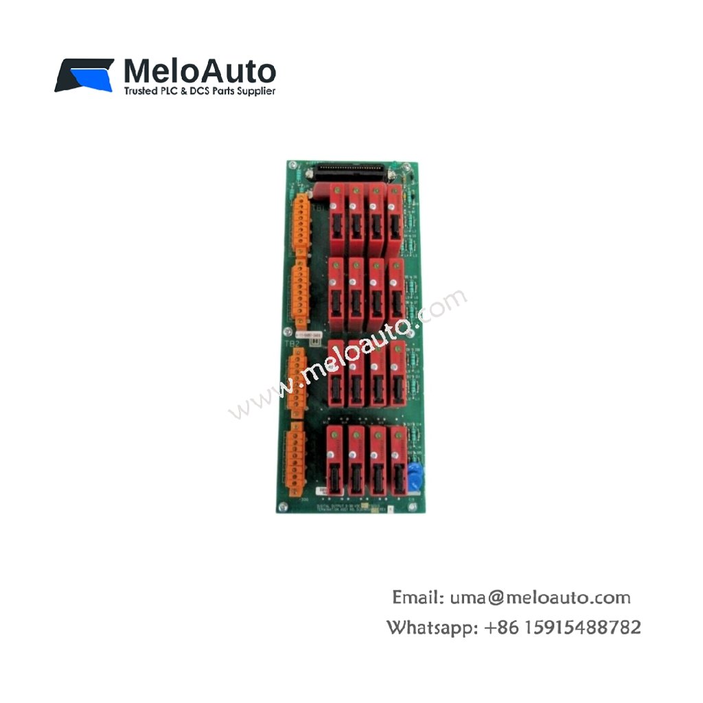
Output Architecture and Channel Design
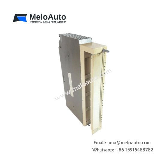
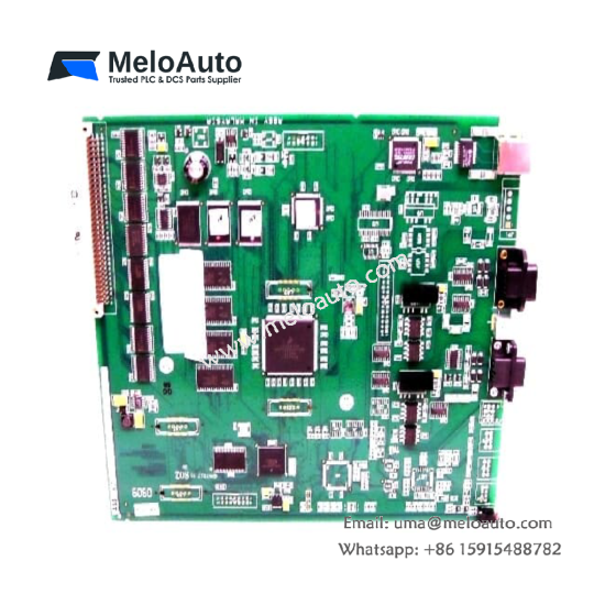
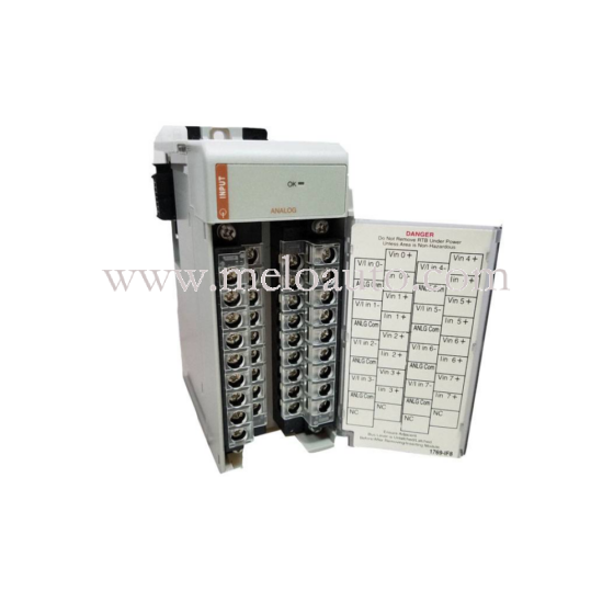
This digital output module drives field actuators, solenoids, and indicator lamps directly from the control system. It features sixteen independent output channels with built-in short-circuit protection for each point. Every channel delivers 24 VDC at 0.5 A continuously without derating. The module also incorporates individual LED indicators for real-time output status monitoring. This configuration supports both high-side and low-side switching applications effectively.
Technical Specifications
| Parameter | Specification |
|---|---|
| Model Number | MC-TDODI3 |
| Output Channels | 16 digital outputs |
| Output Voltage | 24 VDC nominal (18–32 VDC range) |
| Output Current | 0.5 A per channel (continuous) |
| Total Current | 8 A maximum (all channels combined) |
| Load Type | Resistive, inductive, or lamp loads |
| Protection | Short-circuit and overcurrent per channel |
| Off-State Leakage | <0.1 mA |
| On-State Voltage Drop | <0.5 V at rated current |
| Switching Speed | 1 ms typical (on/off transition) |
| Isolation | Optical isolation (channel-to-backplane) |
| Isolation Voltage | 1500 VAC |
| Current Draw (Logic) | 200 mA from backplane |
| Power Dissipation | 6.0 W maximum (full load) |
| Operating Temperature | 0°C to +60°C |
| Storage Temperature | –40°C to +85°C |
| Dimensions (H x W x D) | 130 mm x 32 mm x 135 mm |
| Weight | Approximately 0.40 kg |
| Field Termination | 40-pin ribbon cable connector |
| Output Indicators | 16 red LEDs, one per channel |
Protection and Diagnostic Features
Each output channel includes automatic overcurrent shutdown for fault protection. The module resets the affected channel automatically after clearing the fault condition. A watchdog timer monitors the backplane communication link continuously. This timer forces all outputs to a safe state upon communication loss. Diagnostic data flows through the system software for remote troubleshooting.
Field Wiring and Connection Guide
The MC-TDODI3 terminates field wiring through a 40-pin connector assembly. Use the mating cable harness to connect outputs to field devices directly. Each output channel provides two termination points: output signal and return ground. Connect inductive loads with external flyback diodes for voltage spike suppression. This practice protects the output transistors from damaging voltage transients.
Power Requirements and Energy Management
This module draws 200 mA from the 5 VDC logic supply via the backplane. The output power comes directly from the external 24 VDC field supply. Internal storage capacitors maintain output states during brief supply interruptions. Total power dissipation reaches 6.0 W under maximum load conditions. Allow adequate spacing between modules for proper heat dissipation.
Installation and Mounting Procedure
Insert the module into any standard Series T I/O chassis slot. Push firmly until the ejector tabs snap into the locked position. Secure the module using the top and bottom retaining screws. Connect the field wiring harness before energizing the system. Verify the power LED illuminates after applying system voltage.
Environmental Operating Conditions
This output module operates flawlessly in temperatures from 0°C to 60°C. It tolerates relative humidity levels between 5% and 95% non-condensing. The PCB features conformal coating for protection against dust and moisture. This construction suits industrial environments with moderate contamination levels. Ensure proper cabinet ventilation for reliable long-term operation.
Maintenance and Troubleshooting Tips
Monitor the channel LEDs to verify correct output activation during operation. Replace the module immediately if multiple outputs fail to respond. Check the external power supply voltage if all outputs remain inactive. Clean the connector pins carefully during routine maintenance procedures. Keep spare modules available for quick replacement during emergencies.






WeChat
Scan the QR Code with wechat