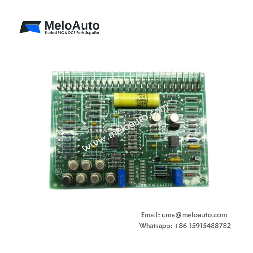
The GE IC693CHS391C serves as a passive mounting plate for Series 90-30 systems. This expansion plate adds four extra slots to your existing rack. You will find it in PLC systems that need more I/O capacity. It connects directly to the main baseplate through a ribbon cable. Therefore, this unit allows system growth without replacing the entire rack.
This plate measures 300 mm in width and 150 mm in height. Its depth reaches 120 mm for standard panel mounting. The unit weighs approximately 1.2 kilograms. It contains no active electronic components at all. Five plastic slot guides hold individual I/O modules securely. Additionally, you get a backplane PCB with four card-edge connectors.
Key Technical Specifications
| Parameter | Value |
|---|---|
| Manufacturer | GE Fanuc Automation |
| Model | IC693CHS391C |
| Product Type | Expansion Plate / Baseplate |
| Number of Slots | 4 |
| Width | 300 mm |
| Height | 150 mm |
| Depth | 120 mm |
| Weight | 1.2 kg |
| Internal Components | 0 (passive) |
| Card-edge Connectors | 4 |
| Slot Guides | 5 (plastic) |
| Energy Storage | 0 Joules (none) |
| Backplane Type | 4-layer PCB |
| Mounting Method | Panel screw-mount |
| Requires | Ribbon cable to main rack |
Internal Architecture and Energy Storage
The GE IC693CHS391C stores absolutely no electrical energy internally. It contains no capacitors, batteries, or inductors. Four card-edge connectors provide the physical interface for I/O modules. These connectors tie together through a passive backplane PCB. The backplane uses four copper layers for signal routing. One layer carries +5 VDC power distribution. Another layer handles the I/O bus communication lines. Each slot guide keeps modules aligned during insertion.
Connection Interfaces and Expansion Method
You will find a 50-pin ribbon cable header on the right side. This header connects the expansion plate to the main CPU rack. Use a shielded 50-conductor ribbon cable for this link. The plate also includes two 24 VDC power input terminals. Connect an external power supply to these terminals. The GE IC693CHS391C then distributes this power to all four slots. Each slot receives +5 VDC at up to 2 amps. The backplane also passes the I/O bus signals between slots.
Installation and Mounting Steps
You mount this expansion plate onto a flat metal panel first. Use four M4 screws through the corner mounting holes. Position the plate at least 50 mm from other equipment. Then, connect the ribbon cable between this plate and the main rack. Plug the 50-pin connector until the latch clicks. Next, wire the 24 VDC supply to the power terminals. Install your I/O modules into the four empty slots. Slide each module firmly until the locking tab engages. Finally, label each slot for easy maintenance identification.


 Analog I/O Module")


WeChat
Scan the QR Code with wechat