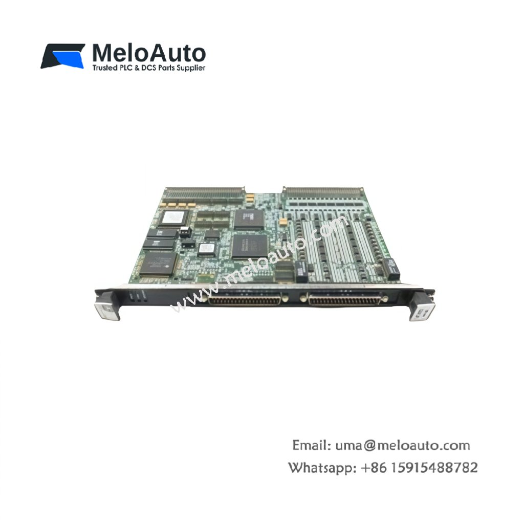
The GE IC610MDL157B provides 16 sinking outputs for Series One PLC systems. This module switches 24 VDC loads to ground through field devices. You will find it in conveyor systems, packaging machines, and assembly lines. It offers optical isolation between the backplane and output circuits. Therefore, this unit protects the CPU from electrical noise.
This module measures 120 mm in height and 85 mm in width. Its depth reaches 110 mm for standard rack mounting. The unit weighs approximately 0.33 kilograms. It contains 16 independent power transistors for sinking operation. Each transistor handles 0.5 amps of continuous current. Additionally, you get 16 green LEDs for channel status indication.
Key Technical Specifications
| Parameter | Value |
|---|---|
| Manufacturer | GE Fanuc Automation |
| Model | IC610MDL157B |
| Product Type | Sink Output Module |
| Number of Outputs | 16 |
| Output Type | Sinking (NPN) |
| Output Voltage | 24 VDC |
| Output Current | 0.5 A per channel |
| Total Current | 8 A (maximum) |
| Off-State Leakage | 0.1 mA maximum |
| Response Time | 1.5 ms (on/off) |
| Internal Drivers | 16 (NPN transistors) |
| Protection | Short circuit, overtemp |
| Height | 120 mm |
| Width | 85 mm |
| Depth | 110 mm |
| Weight | 0.33 kg |
| Status LEDs | 16 (green) |
| Energy Storage | ≈ 90 µF (capacitive) |
| Power Consumption | 220 mA @ 5 VDC |
| Operating Temperature | 0°C to +60°C |
Internal Architecture and Energy Storage
The GE IC610MDL157B stores minimal energy in its output suppressor circuits. Small ceramic capacitors hold approximately 90 microfarads total capacitance. Each output channel uses an NPN power transistor in open-collector configuration. This configuration connects the output to ground when active. Sixteen optocouplers isolate the logic backplane from field wiring. When the CPU turns on a channel, the optocoupler activates. The transistor then switches the output to ground potential. Each channel includes a flyback diode for inductive load protection. This diode safely dissipates energy from relays or solenoids.
Connection Interfaces and Wiring Details
You will find a removable 20-pin terminal block on the bottom face. This block accepts 16 output wires plus four common return terminals. Connect the external 24 VDC supply positive to each load first. Then, connect each load return wire to the output terminal. Use 16 to 22 AWG copper wire for all field connections. The GE IC610MDL157B requires an external 24 VDC power supply. Do not exceed 0.5 amps per channel or 8 amps total. Sixteen green LEDs light up when their respective output turns on. Each LED provides immediate visual feedback for troubleshooting faulty circuits.
Installation and Configuration Steps
You mount this module directly into a Series One I/O rack. First, align the module with the upper and lower slot guides. Then, push it firmly until the backplane connector seats completely. Secure the module with the top and bottom retaining clips. Connect all field wiring before applying power to the system. The GE IC610MDL157B requires no jumpers or dip switch settings. Use the PLC programming software to control each output point individually. The module draws 220 mA from the +5 VDC backplane supply. Always install a suppression diode across each inductive load. Test each output with a multimeter before connecting expensive equipment.


 Analog I/O Module")


WeChat
Scan the QR Code with wechat