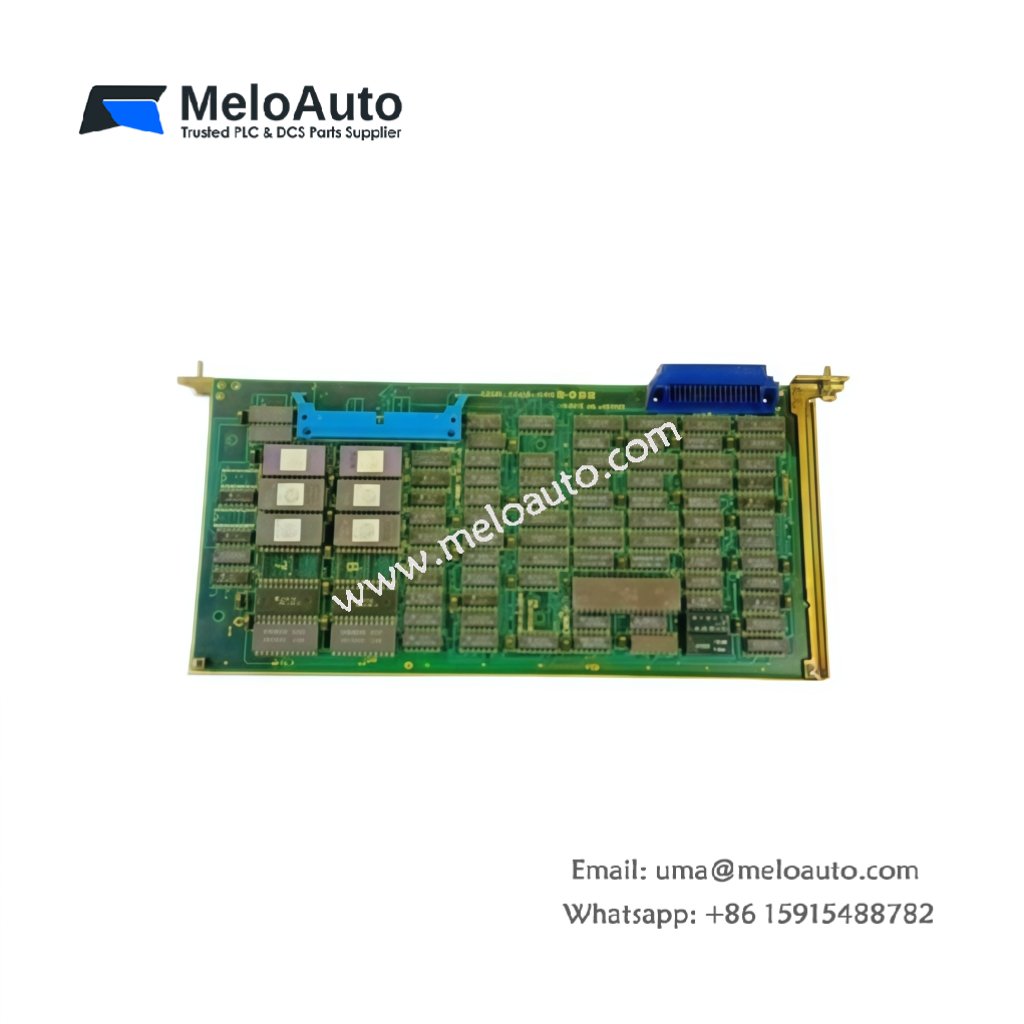
This circuit board provides interface and control functions within a CNC rack. The GE A20B-0008-0440/03A handles communication between multiple CNC modules on the backplane. It measures 250 mm in width and 200 mm in height. This unit weighs approximately 0.45 kg for cabinet mounting.
Technical Specifications Table
| Parameter | Value |
|---|---|
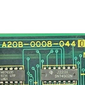
| Product Model | GE A20B-0008-0440/03A |
| Brand | GE Fanuc |
| Category | Rack Circuit Board / CNC Backplane Interface |
| Compatible Series | GE Fanuc CNC Systems |
| PCB Layers | 6-layer circuit board |
| Surface Finish | Gold-plated pads and edge connector |
| Dimensions (W x H x D) | 250 mm x 200 mm x 20 mm |
| Weight | 0.45 kg |
| Connector Types | 1 x 96-pin DIN, 3 x 20-pin headers, 2 x ribbon ports |
| Internal Components | 1 x bus controller, 4 x buffer ICs, 2 x memory chips |
| Memory Type | Flash ROM (256 KB) + SRAM (128 KB) |
| Energy Storage | 1 x 0.1 F super capacitor (data retention: 48 hours) |
| Bus Interface | Proprietary CNC backplane bus |
| Clock Speed | 16 MHz |
| Operating Voltage | 5 V DC |
| Power Consumption | 300 mA maximum |
| LED Indicators | 2 x status (Power, Run) |
| Operating Temperature | 0°C to 55°C |
Internal Design and Backplane Communication
This rack circuit board uses a 6-layer PCB with gold-plated edge connectors. A bus controller manages data flow between multiple CNC modules. The GE A20B-0008-0440/03A buffers and distributes signals across the backplane. Four buffer ICs drive signals to various slots within the rack. Flash memory stores configuration data for the bus controller. A super capacitor retains critical settings for 48 hours without power. Consequently, this board ensures reliable communication between CNC system components.
Installation and Configuration Guide
First, mount this circuit board onto standoffs inside your CNC rack enclosure. Next, slide the board into the backplane slot using the 96-pin edge connector. Then, connect ribbon cables to matching headers on adjacent boards. Connect 5 V DC power supply to the designated terminals. Verify all connector orientations before applying power to the board. The module automatically initializes when you power up the system. Two LED indicators show power and run status. This rack circuit board works with GE Fanuc CNC systems and compatible rack modules. Always use a grounded ESD strap when handling this board to prevent static damage.


 Analog I/O Module")


WeChat
Scan the QR Code with wechat