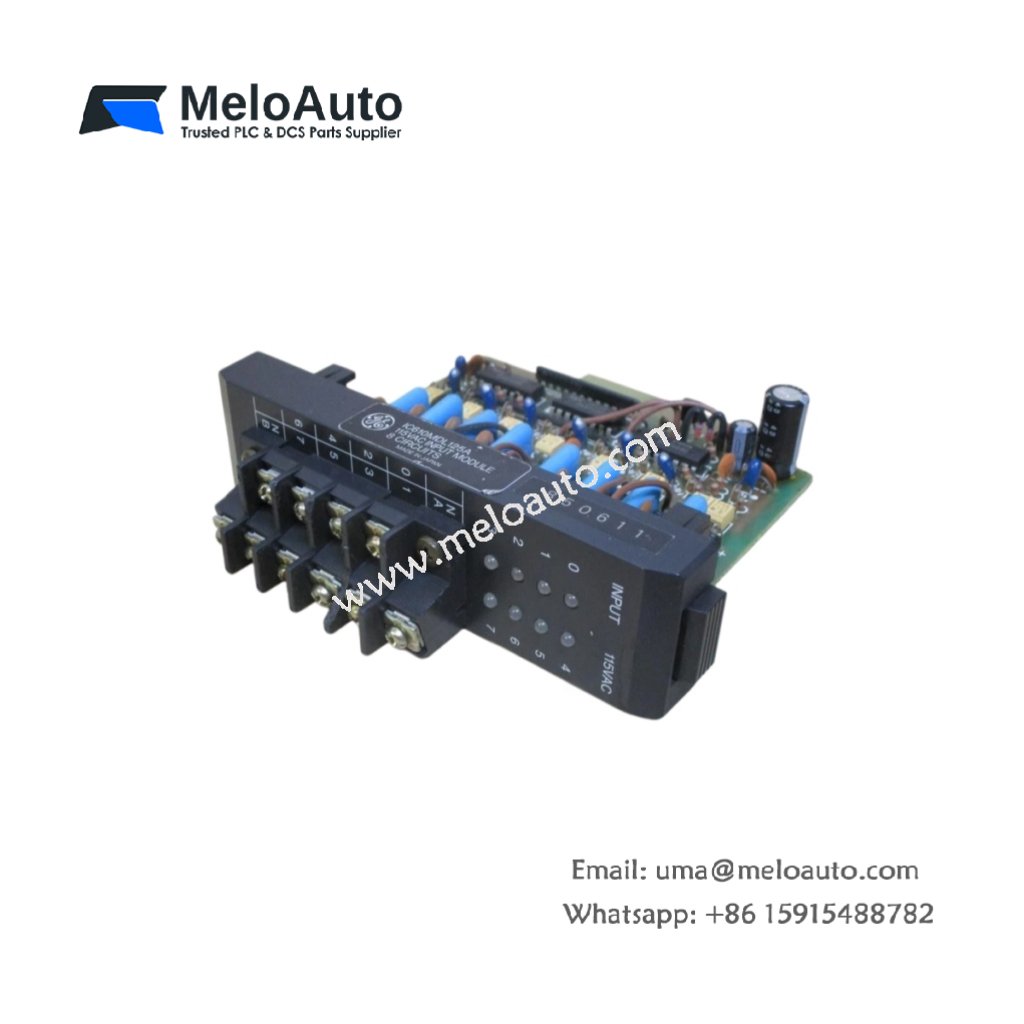
The GE DS200CVMAG1A DS200CVMAG1AEB provides voltage and frequency regulation for turbine-driven generators. This board monitors three-phase power and adjusts excitation accordingly. Therefore, it maintains synchronism with the utility grid under varying loads.
Product Overview
We designed this control board for reliable performance in power plant environments. Its single-processor architecture delivers deterministic control for critical generator functions. Moreover, this unit serves as a direct replacement for earlier CVMAG revisions.
Technical Specifications
| Parameter | Specification |
|---|---|
| Dimensions | 30.5 cm (length) x 16.5 cm (width) |
| Weight | 0.81 kg (approximately 1.79 lb) |
| Interface Type | Dual 64-pin backplane connectors plus front test points |
| Component Count | 248 components including 32-bit CPU and ADC array |
| Energy Storage | 6 aluminum capacitors (470 µF each) plus 2 tantalum capacitors |
| Processor | 32-bit at 32 MHz with hardware floating point |
| Memory | 256 KB SRAM, 512 KB flash, 4 KB EEPROM |
| Analog Inputs | 8 channels: 3 voltage, 3 current, 2 auxiliary |
| Digital Outputs | 8 relay outputs for exciter field control |
| Control Frequency | 50 ms for AVR, 100 ms for governor interface |
| Voltage Sensing | 0-150V AC direct, 0-600V AC with PT inputs |
Core Control Functions
The GE DS200CVMAG1A DS200CVMAG1AEB handles automatic voltage regulation as its primary task. It also manages reactive power sharing for parallel generator operation. Additionally, the board provides under-frequency and over-excitation protection. You can enable or disable each protective function through software.
Energy Storage Components
Six aluminum capacitors filter the incoming DC power for stable operation. Two tantalum capacitors store energy for the real-time clock circuit. The real-time clock maintains event time stamps during power outages. Therefore, you can review fault records accurately after any disturbance.
Input Signal Conditioning
Three voltage inputs accept direct connection to potential transformers. Three current inputs connect to generator CTs for load measurement. Two auxiliary inputs accept 0-10V signals for external setpoints. All eight channels share a common isolated ground reference. This simplifies wiring by using a single return path for all signals.
Installation Requirements
Insert this board into any Mark V rack slot with dual backplane connectors. Align the GE DS200CVMAG1A DS200CVMAG1AEB with both upper and lower guide rails. Push the board firmly until you hear both ejector tabs click. Then tighten all four corner screws to ensure vibration resistance.
Commissioning Procedure
Upload the generator nameplate parameters through the serial configuration port. Set the CT and PT ratios to match your field instrument transformers. Perform a no-load voltage build-up test with the field breaker closed. Verify that the measured voltage matches your programmed setpoint. Then close the generator breaker for load testing and tuning.
Application Scope
This turbine board suits steam turbines up to 100 MW rating. It also works with gas turbines in cogeneration applications. Many industrial plants use the GE DS200CVMAG1A DS200CVMAG1AEB for standby generator control. Its robust design handles frequent start-stop cycles without degradation.


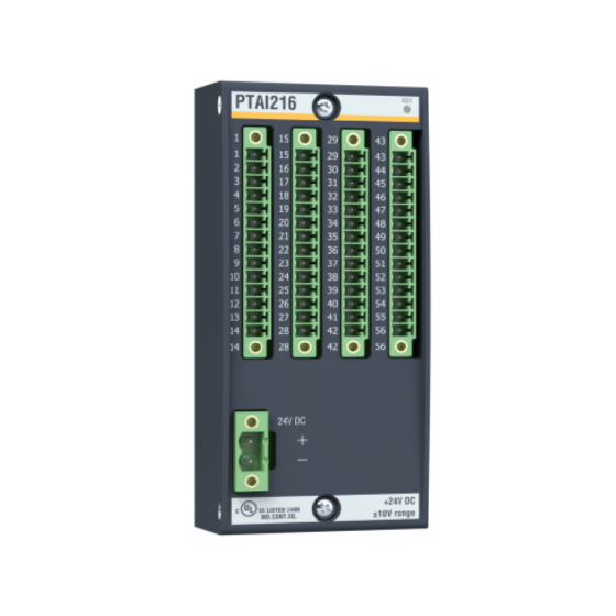


 Analog I/O Module")


WeChat
Scan the QR Code with wechat