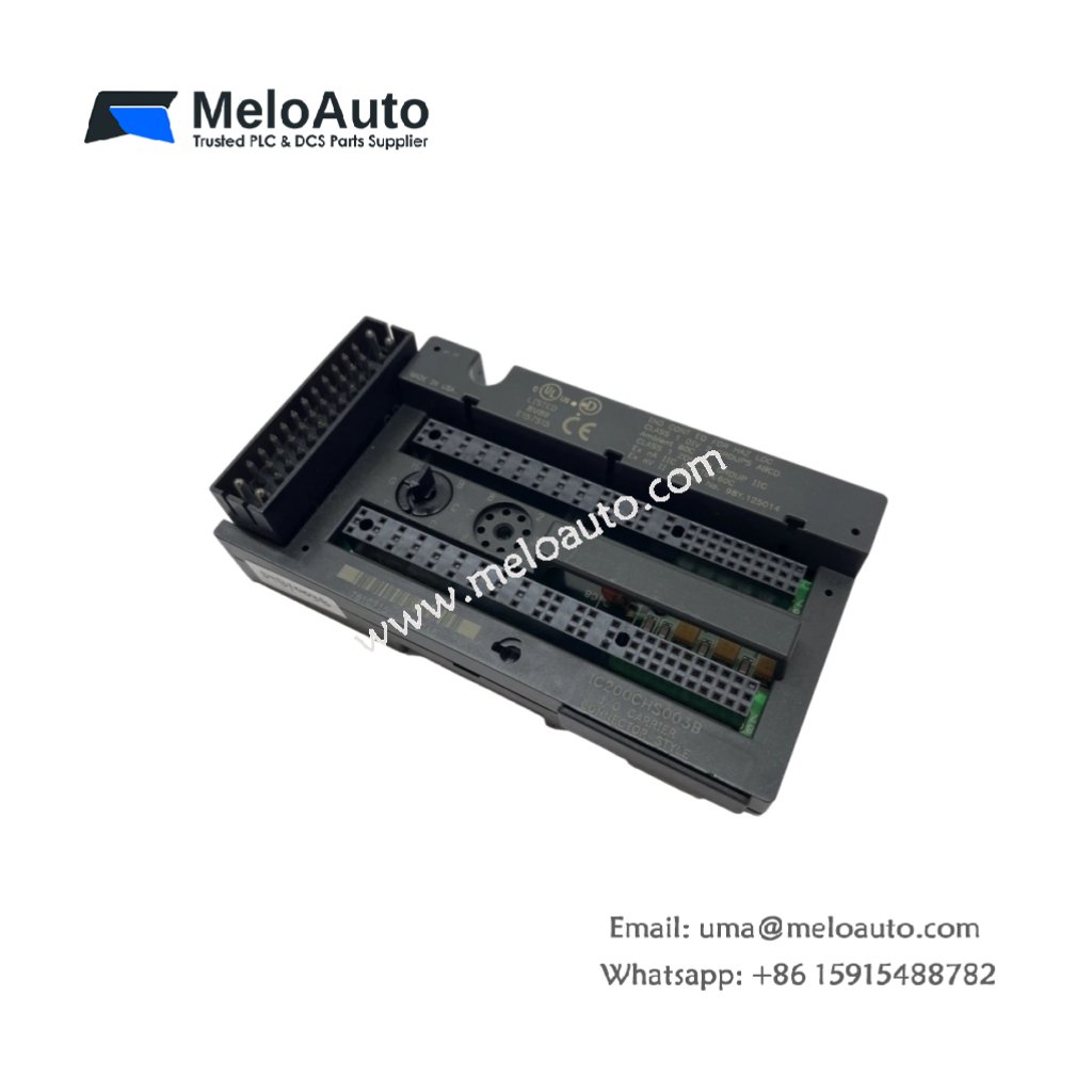
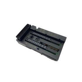
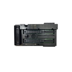
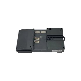
The GE IC200CHS003B provides a mounting base for VersaMax I/O modules. You can install this carrier onto a standard DIN rail in a control cabinet. It holds up to three I/O modules and provides backplane communication. This carrier simplifies system expansion and module replacement tasks.
Technical Specifications and Hardware Layout
This I/O carrier module measures 110 mm in height. Its width reaches 120 mm, and the depth equals 68 mm. The GE IC200CHS003B weighs approximately 0.31 kilograms. The carrier contains a passive backplane with three module slots. It includes no active electronic components or energy storage devices. One 24-pin connector provides the bus interface to the main CPU. Two terminal blocks supply 24 V DC power to the carrier and modules. The carrier requires no internal battery or capacitor maintenance.
| Parameter | Specification |
|---|---|
| Model | GE IC200CHS003B |
| Category | I/O Carrier Module |
| Dimensions (H x W x D) | 110 mm x 120 mm x 68 mm |
| Weight | 0.31 kg |
| Module Slots | 3 |
| Backplane Type | Passive |
| Energy Storage | None |
| Bus Interface | 24-pin connector |
| Power Input | 24 V DC terminals |
| Temperature Range | -20°C to +60°C |
Carrier Capabilities and Compatibility
The GE IC200CHS003B supports all VersaMax I/O module types. It accepts discrete, analog, and specialty modules without restrictions. You can mix different module types within the same carrier. Consequently, this flexibility optimizes I/O configuration for specific applications. The carrier automatically detects inserted modules upon power-up. Each slot provides standard VersaMax backplane signals for seamless integration. The carrier requires an external 24 V DC power supply for all connected modules.
Installation and Practical Guidelines
You must mount this carrier on a DIN rail using the integral clips. Transitioning to wiring, connect the bus cable to the CPU or previous carrier. Provide separate 24 V DC power to the carrier terminal blocks. Ensure proper grounding to avoid noise coupling into the backplane. The carrier requires 25 mm of free space above and below for cooling. The operating temperature range spans from -20°C to +60°C reliably.


WeChat
Scan the QR Code with wechat