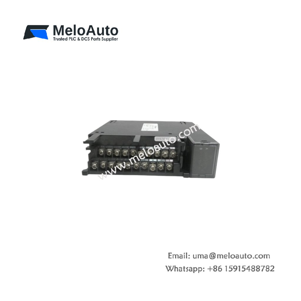
The GE DS200ADCIH1A DS200ADCIH1ADB connects Genius bus networks to Mark V controllers. This board performs protocol conversion between serial bus and parallel backplane. Therefore, it enables distributed I/O for large turbine control systems.
Product Overview
We engineered this adapter board for high-speed data exchange with remote devices. Its single bus port communicates with up to 31 Genius blocks. Moreover, this unit includes diagnostic features for network troubleshooting.
Technical Specifications
| Parameter | Specification |
|---|---|
| Dimensions | 25.4 cm (length) x 16.5 cm (width) |
| Weight | 0.46 kg (approximately 1.01 lb) |
| Interface Type | Single 64-pin backplane plus Genius bus screw terminal |
| Component Count | 182 components including bus controller and memory |
| Energy Storage | 2 aluminum capacitors (1000 µF, 10V) plus 6 ceramic |
| Bus Protocol | Genius LAN at 153.6 kbps fixed |
| Max Nodes | 31 addressable devices |
| Cable Length | 3500 feet (1067 meters) maximum per segment |
| Termination | Built-in 120 ohm switchable resistor |
| Data Buffer | 256 bytes input, 256 bytes output |
| Scan Time | 1.5 ms for 16 nodes, 4 ms for 31 nodes |
Communication Engine
The GE DS200ADCIH1A DS200ADCIH1ADB uses a dedicated microprocessor for bus management. Its two aluminum capacitors store energy for the CPU during power fluctuations. Additionally, the board automatically checks CRC on every received packet. You get error-free data transmission without application-level verification.
Energy Storage Features
Two large aluminum capacitors provide 15 ms of hold-up time. They maintain processor operation during backplane power interruptions. Six ceramic capacitors filter high-frequency noise on all power rails. Clean power ensures reliable communication in electrically noisy environments. Consequently, the board suits applications near variable frequency drives.
Installation Steps
Insert this adapter board into any Mark V I/O slot with 64 pins. Align the GE DS200ADCIH1A DS200ADCIH1ADB with the card guides. Push until the ejector mechanism clicks into locked position. Then secure the board with its two retaining screws. Connect the Genius bus cable to the front terminal block.
Termination Setup
Enable the built-in terminator only for end nodes on the bus. Set switch SW1-1 to ON for terminator activation. Leave SW1-1 OFF for all intermediate devices on the network. The board requires 120 ohm impedance matching for proper operation. Incorrect termination causes data errors and communication timeouts.
Address Configuration
Set the node address using the eight-position dip switch. Switches 1 through 5 select the binary address from 1 to 31. Switch SW1-6 selects normal or extended data buffer mode. Use normal mode for standard Genius I/O blocks. Extended mode supports large data blocks from PLC interfaces. Switch SW1-7 and SW1-8 must remain OFF for proper operation.
Diagnostic Capabilities
The board provides extensive self-test features for network analysis. It can generate loopback packets to verify cable continuity. The diagnostic mode also measures signal strength on the bus. An onboard LED flashes to indicate each received packet. The GE DS200ADCIH1A DS200ADCIH1ADB logs all communication errors in its memory. You can retrieve this log through the backplane interface.
Replacement Information
This board directly replaces older ADCIH versions without hardware changes. Its firmware remains backward compatible with all Genius devices. Many power plants stock the GE DS200ADCIH1A DS200ADCIH1ADB as a spare. Use it in new installations or for upgrading existing Mark V systems.


 Analog I/O Module")


WeChat
Scan the QR Code with wechat