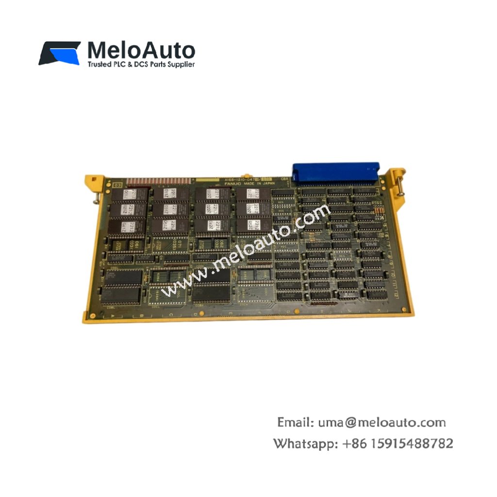
The GE DS200ACNAG1A DS200ACNAG1ADD provides ARCNET network connectivity for Mark V systems. This board links multiple drive controllers into a single high-speed communication network. Therefore, it enables coordinated operation across large industrial automation systems.
Product Overview
We designed this network board for deterministic token-passing communication between nodes. Its ARCNET protocol guarantees data delivery within predictable time frames. Moreover, this unit supports both coaxial and fiber optic physical media.
Technical Specifications
| Parameter | Specification |
|---|---|
| Dimensions | 25.4 cm (length) x 16.5 cm (width) |
| Weight | 0.44 kg (approximately 0.97 lb) |
| Interface Type | Single 64-pin backplane plus BNC and ST fiber connectors |
| Component Count | 168 components including ARCNET controller and transceiver |
| Energy Storage | 4 aluminum capacitors (100 µF, 25V) plus 8 ceramic |
| Network Protocol | ARCNET (ANSI 878.1) token-passing |
| Data Rate | 2.5 Mbps standard |
| Max Nodes | 255 addressable stations per network |
| Cable Type | RG-62 coaxial or multimode fiber |
| Coax Length | 2000 feet (610 meters) maximum |
| Fiber Length | 6500 feet (1980 meters) maximum |
| Token Timeout | 840 ms configurable |
Network Architecture
The GE DS200ACNAG1A DS200ACNAG1ADD manages token passing between all network nodes. Its four aluminum capacitors filter power supply noise for stable transceiver operation. Additionally, the board automatically regenerates the token when a node drops offline. You get automatic network recovery without any operator intervention.
Energy Storage Function
Four aluminum capacitors provide 20 ms of hold-up for the ARCNET controller. They maintain network timing during brief backplane power interruptions. Eight ceramic capacitors decouple high-frequency noise from each IC power pin. Clean power ensures accurate token timing across the entire network. Consequently, data collisions cannot occur with proper board operation.
Installation Steps
Insert this board into a dedicated communications slot in the rack. Align the GE DS200ACNAG1A DS200ACNAG1ADD with its guide rails carefully. Push the board forward until the backplane connector seats fully. Then tighten the two retaining screws to lock the board in place. Connect the network cable to the appropriate front panel connector.
Node Addressing
Set the station address using the eight-position dip switch bank. Switches 1 through 8 define the binary address from 1 to 255. Address 0 serves as a broadcast address for all network nodes. Address 255 acts as the diagnostic node for network testing. No two stations can share the same address on the same network. The board reads the dip switches only during power-up.
Termination Requirements
For coaxial networks, terminate both ends of the backbone cable. Install a 93 ohm terminator at each physical cable end. For fiber networks, termination occurs automatically within each node. Do not add external terminators to fiber optic connections. The GE DS200ACNAG1A DS200ACNAG1ADD provides status LEDs for termination verification.
Network Configuration
Set the baud rate through software configuration only. The default rate of 2.5 Mbps works for most installations. You can select 156 kbps, 625 kbps, or 5 Mbps for special applications. However, all nodes on the same network must use identical rates. The board uses the maximum token timeout of 840 ms by default. Reduce this value for networks with fewer than 32 nodes.
Status Indication
Monitor the three front panel LEDs for network health. Green LED flashes for each token the board receives. Yellow LED illuminates when the board transmits data packets. Red LED indicates a network fault or missing terminator. The GE DS200ACNAG1A DS200ACNAG1ADD also sets a backplane fault bit. Your control logic can monitor this bit for alarm generation.


, and optical isolation for high-speed industrial automation.")
")


WeChat
Scan the QR Code with wechat