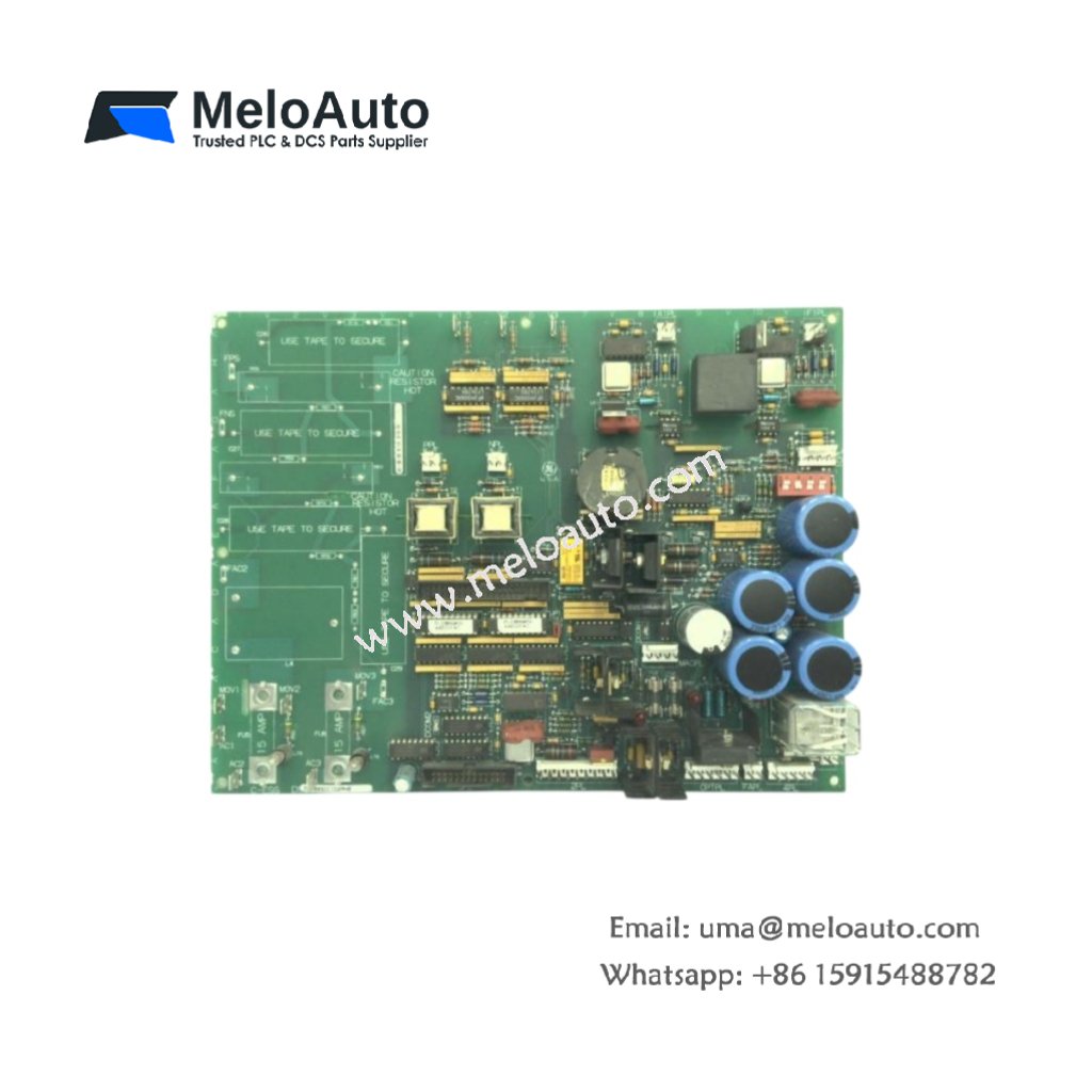
This GE DS200ACNAG1A DS200ACNAG1ADD ARCNET Board manages high-speed deterministic communication between Mark V controllers. The board implements the ARCNET protocol for real-time data exchange across the system. You will find this component in many GE turbine control networks. The DS200ACNAG1ADD variant includes a conformal coating for moisture-prone installations.
Technical Specifications
| Parameter | Specification |
|---|---|
| Full Model | GE DS200ACNAG1A DS200ACNAG1ADD ARCNET Board |
| Category | ARCNET Board |
| Communication Protocol | ARCNET (ANSI 878.1) |
| Data Rate | 2.5 Mbps |
| Interface Type | Coaxial (BNC) or Fiber Optic |
| Maximum Nodes | 255 per Network Segment |
| Packet Size | 0 to 508 Bytes |
| Dimensions (H x W) | 230 mm x 150 mm |
| Weight | Approximately 0.65 kg |
| Connectors | 2 x BNC, 1 x Fiber Optic Transceiver |
| Component Count | 134 Discrete Components |
| Energy Storage | 3 x 33 µF Decoupling Capacitors |
Network Protocol and Data Handling
The GE DS200ACNAG1A DS200ACNAG1ADD ARCNET Board uses token passing to avoid data collisions. Each node waits for the token before transmitting any information. The board handles CRC error checking and automatic retransmission of corrupted packets. Furthermore, it supports both coaxial and fiber optic physical media. Consequently, you can build networks up to 4 km using fiber optic cables.
Installation and Connection Steps
Mount this GE DS200ACNAG1A DS200ACNAG1ADD ARCNET Board in any Mark V rack slot. First, connect the coaxial cable to the BNC connector for electrical networks. Alternatively, attach fiber optic cables for longer distances up to 4 km. After that, set the node ID using the eight-position DIP switch. Finally, apply power and verify the network status LED illuminates green.
Energy Discharge and Safety Notice
This GE DS200ACNAG1A DS200ACNAG1ADD ARCNET Board stores minimal energy in its capacitors. However, you must wait 30 seconds after power removal before handling. The three decoupling capacitors discharge through internal resistors during this time. Never disconnect network cables while the board remains powered.
Status Indication and Diagnostics
A green LED indicates normal network activity and token passing. A yellow LED flashes when this board transmits data packets. A red LED signals a node ID conflict or cable fault. These indicators help technicians resolve network issues quickly without special analyzers.


 Analog I/O Module")


WeChat
Scan the QR Code with wechat