 MeloAuto-Trusted PLC & DCS Parts Supplier
Input Architecture and Channel Configuration
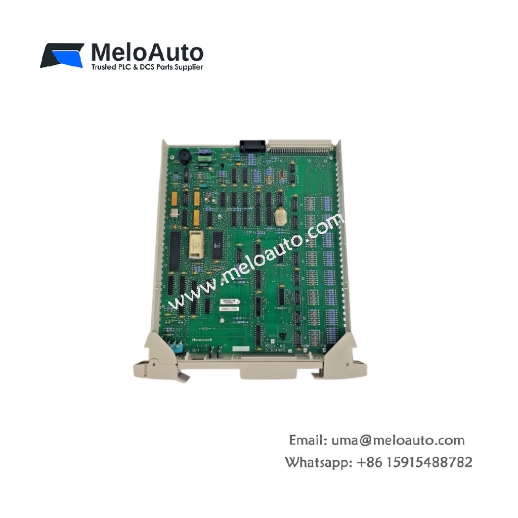
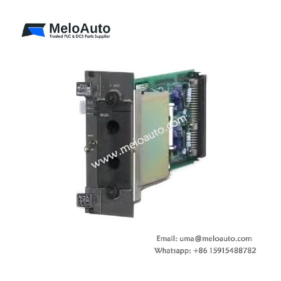
This digital input board provides reliable signal acquisition from field sensors and switches. It features sixteen independent channels arranged in two isolated groups of eight channels each. Every channel accepts 24 VDC signals while providing optical isolation from the control system. The board also includes a built-in loop test facility for verifying field wiring integrity. This feature reduces commissioning time and simplifies troubleshooting procedures.
Technical Specifications
| Parameter | Specification |
|---|---|
| Model Number | 51304485-150 MC-PD1X02 |
| Input Channels | 16 digital inputs |
| Input Groups | 2 isolated groups (8 channels each) |
| Nominal Voltage | 24 VDC |
| Input Range | 18–32 VDC |
| On-State Threshold | >15 VDC |
| Off-State Threshold | <5 VDC |
| Input Impedance | 4.7 kΩ typical |
| Group Isolation | 500 VDC (group-to-group) |
| Channel-to-Backplane Isolation | 1500 VAC |
| Response Time | 2 ms typical (on/off) |
| Current Consumption | 160 mA from 5 VDC backplane |
| Power Dissipation | 4.5 W maximum |
| Operating Temperature | 0°C to +60°C |
| Storage Temperature | –40°C to +85°C |
| Dimensions (H x W x D) | 130 mm x 32 mm x 150 mm |
| Weight | Approximately 0.42 kg |
| Field Termination | 40-pin ribbon cable connector |
| Status Indicators | 16 green LEDs plus one group status LED |
Signal Processing and Input Filtering
Each channel incorporates a programmable debounce filter for suppressing switch bounce. The filter time ranges from 0 ms to 100 ms through software configuration. This board also detects pulse signals with a minimum width of 2 ms. A change-of-state feature captures rapid input transitions accurately. The filter settings remain stored in non-volatile memory after power cycling.
Field Wiring and Termination Interface
The 51304485-150 MC-PD1X02 connects to field devices through a 40-pin ribbon cable assembly. Each input channel requires two connections: signal input and common return. The board supports both sinking and sourcing field device configurations. Connect shielded cables to the designated shield terminal for noise immunity. Proper grounding practices ensure stable operation in electrically noisy environments.
Power Requirements and Energy Storage
This board draws 160 mA from the 5 VDC system backplane supply. Internal capacitors store sufficient energy to bridge brief power interruptions. The module retains input state information during momentary supply dips. Total heat dissipation reaches 4.5 W under full input load. This efficiency maintains acceptable temperature levels inside the cabinet.
Installation and Mounting Procedure
Insert the board into any available Series T I/O chassis slot. Press firmly until the ejector tabs engage securely with the chassis. Tighten the two retaining screws to secure the board mechanically. Connect the field wiring harness after completing the board installation. Verify the power LED illuminates immediately after system energization.
Environmental and Mechanical Specifications
This board operates reliably in temperatures from 0°C to 60°C. It withstands relative humidity ranging from 5% to 95% non-condensing. A conformal coating protects the PCB from moisture and airborne contaminants. The board’s compact footprint saves valuable cabinet space. Its lightweight construction simplifies handling during installation and replacement.
Diagnostics and Maintenance Features
Front-panel LEDs indicate each channel’s real-time on/off status clearly. The system software retrieves comprehensive diagnostic data through the backplane. Replace the board promptly if any channel exhibits erratic behavior. Perform routine visual inspections of connectors and wiring periodically. Keep a spare board on hand for quick replacement during critical operations.





WeChat
Scan the QR Code with wechat