 MeloAuto-Trusted PLC & DCS Parts Supplier
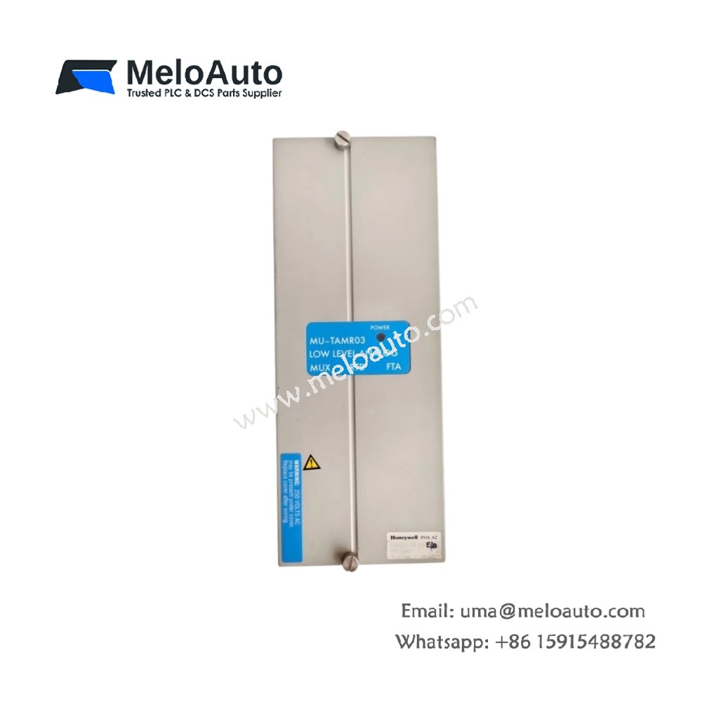
Input Architecture and Measurement Capability
This analog input module delivers precise signal acquisition for four isolated channels. Each channel accepts 4–20 mA or 0–20 mA current inputs directly. The module also accommodates 0–10 VDC voltage signals through simple configuration changes. A built-in 16-bit ADC ensures high-resolution measurements across the entire range. This versatility makes it suitable for diverse process monitoring applications.
Technical Specifications
| Parameter | Specification |
|---|---|
| Model Number | 501309218-125 MU-TAMR03 |
| Input Channels | 4 isolated analog inputs |
| Resolution | 16 bits |
| Signal Types | 4–20 mA, 0–20 mA, 0–10 VDC |
| Input Impedance (Current) | 250 Ω |
| Input Impedance (Voltage) | 10 MΩ |
| Accuracy | ±0.05% of full scale at 25°C |
| Temperature Coefficient | ±50 ppm/°C |
| Isolation Voltage | 1500 VAC channel-to-backplane |
| Common Mode Rejection | >90 dB at 60 Hz |
| Normal Mode Rejection | >50 dB at 60 Hz |
| Conversion Time | 100 ms per channel (max) |
| Current Draw | 150 mA from 5 VDC backplane |
| Power Dissipation | 3.5 W maximum |
| Operating Temperature | 0°C to +60°C |
| Storage Temperature | –40°C to +85°C |
| Dimensions | 130 mm x 32 mm x 145 mm |
| Weight | Approximately 0.38 kg |
| Termination Interface | 40-pin ribbon cable |
| LED Indicators | Per-channel status + power |
Signal Conditioning and Filtering
Each channel incorporates a programmable low-pass filter for noise attenuation. The module performs automatic calibration to maintain long-term measurement stability. A differential amplifier rejects common mode voltage effectively. The analog front-end includes overvoltage protection for each input. This protection safeguards the module against accidental wiring errors.
Field Wiring and Connection Details
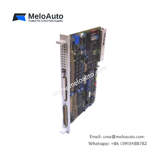
The 501309218-125 MU-TAMR03 terminates field wiring through a 40-pin cable assembly. Each channel requires three termination points: signal positive, signal negative, and shield. Connect the cable shield to the module’s designated ground terminal. Use twisted-pair wiring to minimize electromagnetic interference pickup. Maintain proper separation from high-voltage AC power conduits.
Power Requirements and Energy Management
This module draws 150 mA from the 5 VDC backplane supply. Internal storage capacitors support operation during brief power interruptions. The module retains configuration data in non-volatile memory. Total power dissipation reaches 3.5 W under maximum load. This low power consumption reduces cabinet cooling requirements.
Installation and Mounting Procedure
Insert the module into any standard Series T chassis slot. Push the module until the ejector tabs lock securely. Fasten the retaining screws at the top and bottom. Connect the field termination cable after mechanical installation. Observe the power LED to confirm correct system energization.
Environmental Performance
This module operates reliably across a 0°C to 60°C ambient range. It tolerates relative humidity from 5% to 95% without condensation. A conformal coating protects the PCB from environmental contaminants. This rugged construction suits refinery and chemical plant installations. Ensure adequate clearance for airflow around the module.
Diagnostics and Service Guidelines
Front-panel LEDs provide immediate visual feedback for each channel. The system software offers comprehensive diagnostic data access. Replace the module if measurement errors exceed acceptable limits. Perform periodic calibration using traceable reference standards. Maintain a spare module for emergency replacement scenarios.






WeChat
Scan the QR Code with wechat