 MeloAuto-Trusted PLC & DCS Parts Supplier
Redundancy Architecture and Output Configuration
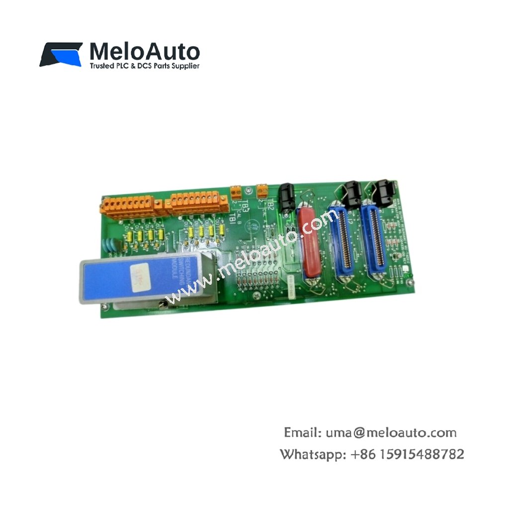
This analog output redundancy board provides fail-safe signal generation for critical control loops. It features twelve analog output channels configured in six redundant pairs. Each pair delivers 4–20 mA signals to field actuators with automatic switchover capability. The board continuously monitors both primary and secondary output health. This architecture ensures uninterrupted process control during module failures.
Technical Specifications
| Parameter | Specification |
|---|---|
| Model Number | MU-TAOX12 51304335-100 |
| Output Channels | 12 (6 redundant pairs) |
| Signal Type | 4–20 mA (sourcing) |
| Resolution | 12 bits (1 LSB = 0.024% of span) |
| Accuracy | ±0.1% of full scale at 25°C |
| Temperature Drift | ±80 ppm/°C |
| Output Load Range | 0–750 Ω |
| Compliance Voltage | 18 VDC minimum at 20 mA |
| Redundancy Mode | Automatic failover |
| Switchover Time | <100 ms typical |
| Channel Isolation | 1500 VAC to backplane |
| Current Draw | 300 mA from 5 VDC backplane |
| Loop Power | External 24 VDC supply |
| Power Dissipation | 6.5 W maximum |
| Operating Temperature | 0°C to +60°C |
| Storage Temperature | –40°C to +85°C |
| Dimensions | 130 mm x 32 mm x 165 mm |
| Weight | Approximately 0.48 kg |
| Termination Interface | 40-pin ribbon cable |
| Status LEDs | Pair health + individual channel |
Redundancy Operation and Failover Logic
The MU-TAOX12 51304335-100 actively monitors each channel’s output current and loop integrity. It automatically transfers control to the backup channel upon detecting a primary failure. The board also supports manual switchover through system software commands. Diagnostic data flows continuously to the controller for process monitoring. This redundancy scheme eliminates single-point failures in safety-critical applications.
Wiring and Termination Interface
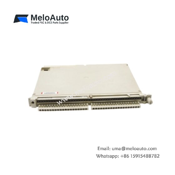
This redundancy board connects to field devices via a 40-pin ribbon cable assembly. Each redundant pair requires termination connections for both primary and backup signals. The board provides dedicated terminals for each channel’s output and return. Connect the external 24 VDC supply to the designated power input terminals. Use shielded twisted-pair cables to minimize EMI susceptibility.
Power Architecture and Energy Buffering
This board draws 300 mA from the 5 VDC logic supply from the backplane. It also requires an external 24 VDC loop power supply for current sourcing. Internal capacitors store energy to maintain output during supply transitions. Total power dissipation reaches 6.5 W under full load conditions. Ensure the external power supply meets the 18–32 VDC input range.
Installation and Mounting Instructions
Insert the board into an available Series T I/O chassis slot. Press firmly until the ejector tabs latch into place. Secure the board with the top and bottom retaining screws. Connect the field wiring harness after completing installation. Apply loop power and verify the health LEDs indicate normal operation.
Environmental and Mechanical Durability
This board operates reliably in 0°C to 60°C ambient temperatures. It withstands humidity from 5% to 95% non-condensing without degradation. The PCB includes conformal coating for moisture and dust protection. Its robust construction suits demanding continuous process environments. Maintain adequate clearance between modules for proper airflow.
Diagnostics and Service Procedures
Front-panel LEDs display individual channel health and redundancy status. The system software provides detailed diagnostic logs for troubleshooting. Replace a failed board immediately to maintain full redundancy. Perform loop tests after installing new boards to verify proper switchover. Document all maintenance actions for quality records.






WeChat
Scan the QR Code with wechat