The GE IC200MDL750B provides 16 discrete output channels for VersaMax control systems. This module controls solenoids, relays, and indicator lights from the PLC. Therefore, it interfaces the controller with field actuators in industrial automation.
Product Overview
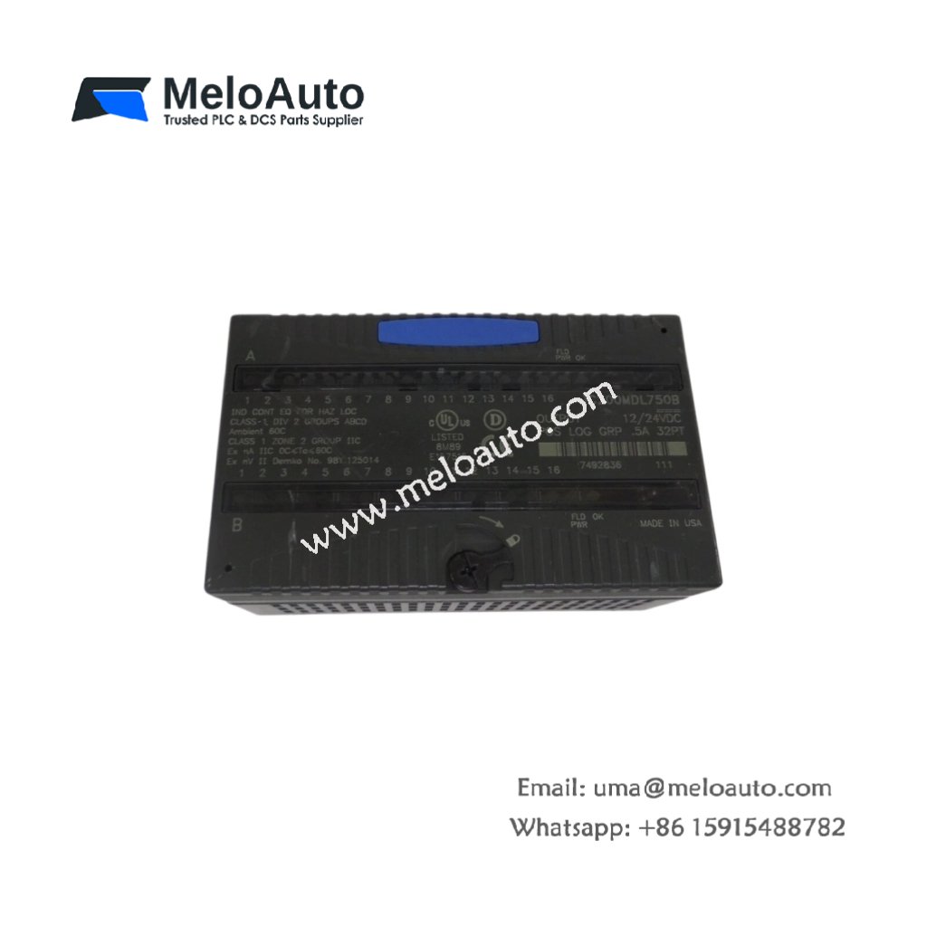
We designed this output module for high-density control in compact cabinets. Its 16 points deliver reliable switching for 24V DC loads. Moreover, this unit includes per-point LED indication for easy troubleshooting.
Technical Specifications
| Parameter | Specification |
|---|---|
| Dimensions | 12.0 cm (height) x 5.0 cm (width) x 8.0 cm (depth) |
| Weight | 0.16 kg (approximately 0.35 lb) |
| Interface Type | Single bus connector plus removable terminal block |
| Component Count | 98 components including MOSFETs and optocouplers |
| Energy Storage | 4 ceramic capacitors (0.1 µF) plus 2 electrolytic (47 µF) |
| Output Channels | 16 discrete outputs, grouped in 8-channel banks |
| Output Type | Sourcing (positive logic) at 24V DC |
| Output Current | 0.5A per channel, 3A per common group |
| Total Current | 6A maximum for all 16 channels |
| Output Voltage | 20.4V to 28.8V DC range |
| Response Time | 1 ms typical from logic to output |
| Protection | Overcurrent and short-circuit per channel |
| Isolation | 1500V RMS between field and logic |
Output Stage Design
The GE IC200MDL750B uses power MOSFETs for each output channel. Its four ceramic capacitors filter noise on the internal logic supply. Additionally, two electrolytic capacitors store energy for brief overload events. You get reliable switching without external suppression components for most loads.
Energy Storage Components
Four ceramic capacitors decouple high-frequency noise from the backplane. Two electrolytic capacitors provide charge for inrush current demands. A typical solenoid draws 1.5A for its initial pull-in period. These capacitors supply that surge without dropping the output voltage. After the inrush, the current drops to the 0.5A holding level.
Installation Steps
Insert this module into any VersaMax I/O slot in the control rack. Align the GE IC200MDL750B with the backplane connector guide. Push the module firmly until its locking tab clicks into position. Then secure the module with the top retaining screw. Connect field wiring to the removable 22-position terminal block.
Channel Grouping
Outputs 0 through 7 share a common return (C0 on terminals 9-10). Outputs 8 through 15 share a second common return (C1 on terminals 19-20). Each common return can carry up to 3A continuously. Distribute high-current loads across both groups for balance. Do not exceed 6A total for all channels combined.
Terminal Assignments
Terminals 1 through 8 connect to output channels 0 through 7.Terminal 21 provides chassis ground for shielding. Terminal 22 is not connected.
Diagnostic Features
The module detects and reports overload conditions on each output. An overload above 0.5A triggers a channel fault indication. The module will shut down the affected channel to prevent damage. After the overload clears, you must cycle power to reset the channel. The PLC receives fault status through the backplane communication bus. A red LED next to each channel indicates a fault condition.
Application Scope
This output module suits conveyor control and packaging machinery. Many factories use the GE IC200MDL750B for valve and motor starter control. Its compact size fits high-density VersaMax racks efficiently.


 Analog I/O Module")


WeChat
Scan the QR Code with wechat