Why This Signal Conditioner Board Converts Sensor Data Accurately
The GE DS200PTCTG1B DS200PTCTG1BAA converts analog sensor signals for Mark V systems. This board conditions voltage and current inputs before sending them to controllers. It provides precise scaling for pressure, temperature, and speed transducers. For this reason, the GE DS200PTCTG1B DS200PTCTG1BAA improves measurement accuracy across all turbine parameters. It also filters out electrical noise from long sensor cables.
Technical Specifications of the Board
We engineer this GE DS200PTCTG1B DS200PTCTG1BAA for precision signal conditioning tasks. It operates on a 24V DC power supply with ±10% tolerance. The board features eight analog input channels with programmable gain settings. Each channel includes a 12‑bit analog‑to‑digital converter for digitization. On‑board capacitors provide energy storage for filtering stages.
| Specification | Value | Additional Notes |
|---|---|---|
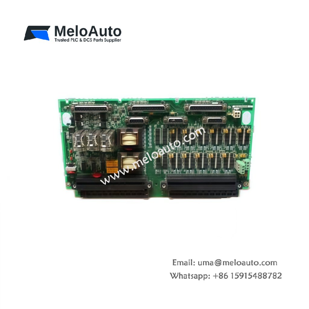
| Full Model | GE DS200PTCTG1B DS200PTCTG1BAA | Signal Conditioner Board |
| Power Supply | 24V DC ±10% | Standard industrial level |
| Analog Inputs | Eight differential channels | 0‑10V or 4‑20mA selectable |
| ADC Resolution | 12‑bit per channel | Provides 4096 count resolution |
| Gain Settings | Programmable from 1 to 100 | Software‑configurable per channel |
| Filtering | Third‑order low‑pass filter | Removes frequencies above 100Hz |
| Energy Storage | On‑board capacitor bank | 1000µF total for filtering |
| Dimensions | 175mm x 105mm x 55mm | Fits Mark V I/O racks |
| Weight | 0.62 kg (approximately) | Moderate weight for stability |
| Interface Type | Backplane connector + terminal block | Shielded for noise rejection |
| Component Count | 78 discrete components | Op‑amps, ADCs, capacitors, resistors |
Hardware Architecture and Signal Processing
The GE DS200PTCTG1B DS200PTCTG1BAA includes a dedicated microcontroller for gain control. This processor configures each channel independently based on sensor type. Moving to input stage, differential amplifiers reject common‑mode noise from field wiring. The board then samples each channel sequentially at 1kHz rate. Moreover, the G1BAA revision adds improved electromagnetic interference shielding. This enhancement maintains accuracy in high‑noise turbine environments.
Installation and Calibration Guidelines
You must de‑energize the control cabinet before removing this board. Remove the GE DS200PTCTG1B DS200PTCTG1BAA from its rack slot carefully. Then insert the replacement board into the exact same slot position. Verify all backplane pins align correctly with the connector. Skipping this step may cause inaccurate sensor readings. Additionally, recalibrate each channel using a known reference signal after installation.


 Analog I/O Module")


WeChat
Scan the QR Code with wechat