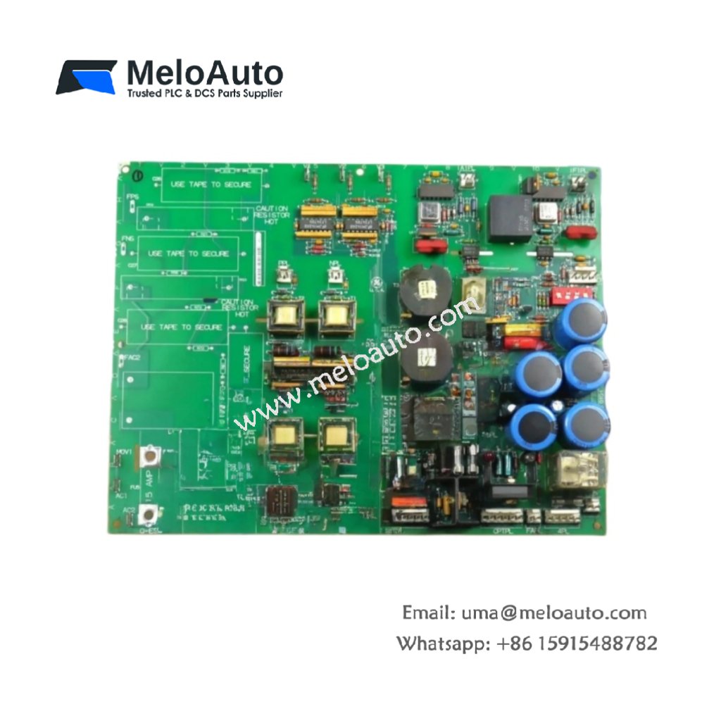
This GE DS200PCCAG1A DS200PCCAG1ADB Power Connect Card distributes DC power across multiple Mark V rack slots. The board receives raw DC input and provides filtered outputs to adjacent cards. You will find this component in many GE turbine control systems worldwide. The DS200PCCAG1ADB variant includes a durable conformal coating for harsh environments.
Technical Specifications
| Parameter | Specification |
|---|---|
| Full Model | GE DS200PCCAG1A DS200PCCAG1ADB Power Connect Card |
| Category | Power Connect Card |
| Input Voltage | 125 VDC or 250 VDC (Field Selectable) |
| Output Voltage | Same as Input (Pass-Through with Filtering) |
| Maximum Current | 20 A Continuous |
| Filtering | 2-Stage LC Low-Pass Filter |
| Distribution Slots | 8 Backplane Connectors |
| Dimensions (H x W) | 160 mm x 100 mm |
| Weight | Approximately 0.35 kg |
| Connectors | 2 x Power Input Stabs, 8 x Edge Connectors |
| Component Count | 52 Discrete Components |
| Energy Storage | 2 x 220 µF Filter Capacitors |
Power Distribution and Filtering Features
The GE DS200PCCAG1A DS200PCCAG1ADB Power Connect Card distributes clean DC power to eight rack slots. A two-stage LC filter removes high-frequency noise from the input supply. Each output path includes a current-limiting fuse for short circuit protection. Furthermore, the board provides status feedback to the main controller. Consequently, the system can monitor power health continuously.
Installation and Connection Steps
Mount this GE DS200PCCAG1A DS200PCCAG1ADB Power Connect Card in the dedicated power slot of any Mark V rack. First, connect the external DC supply to the two power input stabs. After that, slide the board fully into the backplane connectors. Then, secure the board using the front panel retaining screws. Finally, verify the green status LED illuminates before inserting other cards.
Energy Discharge and Safety Notice
This GE DS200PCCAG1A DS200PCCAG1ADB Power Connect Card stores minimal energy in its filter capacitors. However, you must wait 30 seconds after power removal before handling. The two capacitors discharge through internal bleeder resistors during this time. Never insert or remove this card while the system power remains on.
Status Indication and Diagnostics
A single green LED indicates the presence of valid input power. A red LED illuminates when any output fuse has opened due to overload. These simple indicators help technicians verify power distribution quickly without meters.


 Module with 24V DC voltage, ideal for Tricon PLC controllers and critical industrial safety systems.")


 Analog I/O Module")


WeChat
Scan the QR Code with wechat