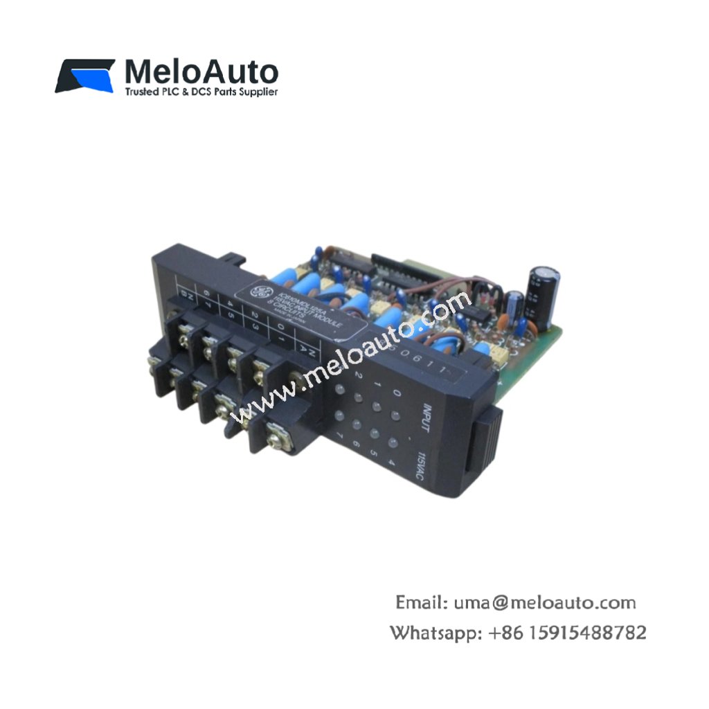
The GE DS200ADPAG1A DS200ADPAG1ABB links Genius field devices to the Mark V controller. This board converts serial bus messages into parallel backplane data. Therefore, it allows seamless integration of distributed I/O networks.
Product Overview
We built this adapter board for reliable communication in harsh industrial zones. Its single bus port connects up to 31 remote devices on one network. Moreover, this unit supports both global data and directed message transfers.
Technical Specifications
| Parameter | Specification |
|---|---|
| Dimensions | 25.4 cm (length) x 16.5 cm (width) |
| Weight | 0.45 kg (approximately 0.99 lb) |
| Interface Type | Single 64-pin backplane plus one Genius bus connector |
| Component Count | 176 components including controller ASIC and drivers |
| Energy Storage | 3 aluminum capacitors (470 µF, 16V) plus 8 ceramic |
| Bus Protocol | Genius LAN at 153.6 kbps only |
| Bus Port | 1 port with auto-negotiating termination |
| Max Nodes | 31 addressable devices per bus |
| Cable Type | Shielded twisted pair, 120 ohm impedance |
| Segment Length | 2500 feet (762 meters) without repeaters |
| Data Mapping | Configurable as 128/128 or 64/192 bytes I/O |
Bus Interface Design
The GE DS200ADPAG1A DS200ADPAG1ABB incorporates a dedicated bus controller chip. Its three aluminum capacitors smooth power delivery to the transceiver section. Additionally, onboard termination resistors activate automatically when needed. You do not need external terminators for most installations. The board senses cable length and enables termination accordingly.
Energy Storage Role
Three aluminum capacitors provide hold-up energy for bus transmissions. They maintain transceiver power during backplane voltage fluctuations. Eight ceramic capacitors filter switching noise from the DC-DC converter. This filtering ensures clean clock signals for the bus timing circuit. Consequently, bit errors remain extremely low even with long cable runs.
Installation Procedure
Insert this adapter board into any standard Mark V I/O slot. Align the GE DS200ADPAG1A DS200ADPAG1ABB with its card guides carefully. Push the board forward until the backplane connector seats fully. Then tighten the two retaining screws to secure the board. Connect the Genius bus cable to the front BNC connector last.
Addressing Configuration
Set the node address using the six-position dip switch block. Switches 1 through 5 set the binary address from 1 to 31. Switch 6 enables or disables the built-in bus terminator. Turn terminator ON only for devices at the physical cable ends. Leave it OFF for all intermediate nodes on the bus. Address 0 serves as a broadcast address for all nodes.
Communication Settings
The board operates at a fixed 153.6 kbps baud rate. You cannot change this speed through dip switches or software. All devices on the same bus must use identical speed settings. The board scans all 31 possible addresses every 2 ms. Each remote device responds within its allocated time slot. Therefore, the total bus scan time depends on the number of active nodes.
Status Monitoring
Watch the three LEDs on the front panel for operational status. Green LED flashes for each packet the board transmits. Yellow LED illuminates when the board receives valid data. Red LED indicates a bus fault or missing terminator. The GE DS200ADPAG1A DS200ADPAG1ABB also sets a backplane fault bit. Your control logic can monitor this bit for alarm generation.
Replacement Scenarios
Many facilities choose this board for new Genius network installations. It directly replaces DS200ADPBG1A units in non-redundant applications. The GE DS200ADPAG1A DS200ADPAG1ABB costs less than dual-port versions. Its single-port design suits small to medium I/O networks perfectly.
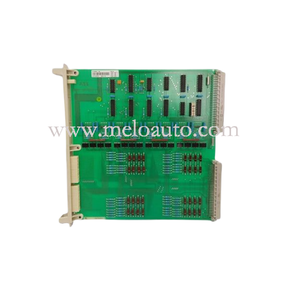


 Analog I/O Module")


WeChat
Scan the QR Code with wechat