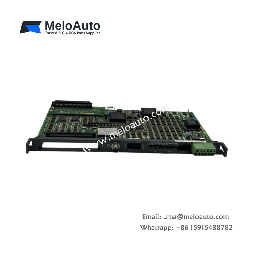
Core Function of This Circuit Board
The GE A20B-8001-0120/02A provides signal routing and power distribution within CNC cabinets. This circuit board serves as an interface between the main controller and peripheral devices. It buffers input signals from operators and machine sensors. Consequently, the module ensures reliable communication across the entire control system.
Physical Dimensions and Board Construction
This circuit board measures 210 mm in total length. Its width reaches 175 mm for a mid-size PCB form factor. The board thickness stands at 18 mm including all component heights. You will find 324 discrete components on this four-layer fiberglass substrate. These include buffer ICs, pull-up resistor networks, and decoupling capacitors. The GE A20B-8001-0120/02A weighs approximately 280 grams for secure mounting.
Signal Interface and Channel Configuration
The GE A20B-8001-0120/02A provides 24 TTL-level input channels for digital signals. It also offers 16 TTL-level output channels for driving indicator LEDs. The board includes 8 open-collector outputs for relay and solenoid control. Each open-collector output sinks up to 100 mA at 24 V DC. A built-in pull-up resistor network sets default logic states for unused inputs.
Voltage Regulation and Power Distribution
This circuit board incorporates three onboard voltage regulators. The first regulator converts 24 V DC input into 5 V DC for logic circuits. The second regulator provides 3.3 V DC for low-voltage ICs. The third regulator supplies 12 V DC for analog signal conditioning. Each regulator includes overcurrent and thermal shutdown protection. The board distributes these voltages through dedicated power planes.
Connector Types and Wiring Interfaces
The GE A20B-8001-0120/02A uses three 34-pin ribbon cable headers for I/O connections. A single 10-pin header accepts the primary 24 V DC power input. Furthermore, the board includes two 6-pin headers for auxiliary signal routing. All connectors use keyed housings to prevent incorrect cable installation. Gold-plated contacts ensure reliable signal integrity in industrial environments.
Component Layout and Test Points
This circuit board arranges components for easy field troubleshooting. Twenty-four status LEDs indicate active input signals on the top edge. Sixteen additional LEDs show output states for immediate visual feedback. The board provides ten labeled test points for voltage verification. These test points include +5 V, +3.3 V, +12 V, and common grounds. A 4-pin header supports external logic analyzer connection for diagnostics.
Energy Storage and Power Requirements
The GE A20B-8001-0120/02A draws 220 mA from a 24 V DC power supply. The onboard regulators then produce all necessary secondary voltages. The board incorporates four 100 µF and six 47 µF electrolytic capacitors. These capacitors filter each voltage rail for noise-free operation. Total stored energy reaches approximately 0.11 joules at nominal voltage.
| Parameter | Specification |
|---|---|
| Model | A20B-8001-0120/02A |
| Brand | GE (General Electric) / Fanuc |
| Category | Circuit Board / Interface Board |
| Length x Width | 210 x 175 mm |
| Thickness | 18 mm |
| Weight | 280 grams |
| Component Count | 324 |
| TTL input channels | 24 |
| TTL output channels | 16 |
| Open-collector outputs | 8, 100 mA at 24 V DC |
| Onboard regulators | 3 (24V to 5V, 3.3V, 12V) |
| Input power | 24 V DC at 220 mA |
| Main I/O connectors | 3 x 34-pin ribbon cable |
| Power input connector | 1 x 10-pin header |
| Auxiliary connectors | 2 x 6-pin header |
| Status LEDs (inputs) | 24 |
| Status LEDs (outputs) | 16 |
| Test points | 10 (voltages and ground) |
| Filter capacitors | 4 x 100 µF, 6 x 47 µF |
| Total stored energy | 0.11 Joules |
| Logic analyzer header | 4-pin |
| Protection features | Overcurrent, thermal shutdown |
| Operating temperature | 0°C to +55°C |
Installation and Troubleshooting Notes
You must mount this board in a clean, dry CNC cabinet environment. Always verify the input voltage polarity before connecting the power cable. Then, check that each LED illuminates correctly for active signals. The board requires no firmware updates or software configuration. Regular inspection of test points ensures all voltage rails remain within tolerance.


 Analog I/O Module")


WeChat
Scan the QR Code with wechat