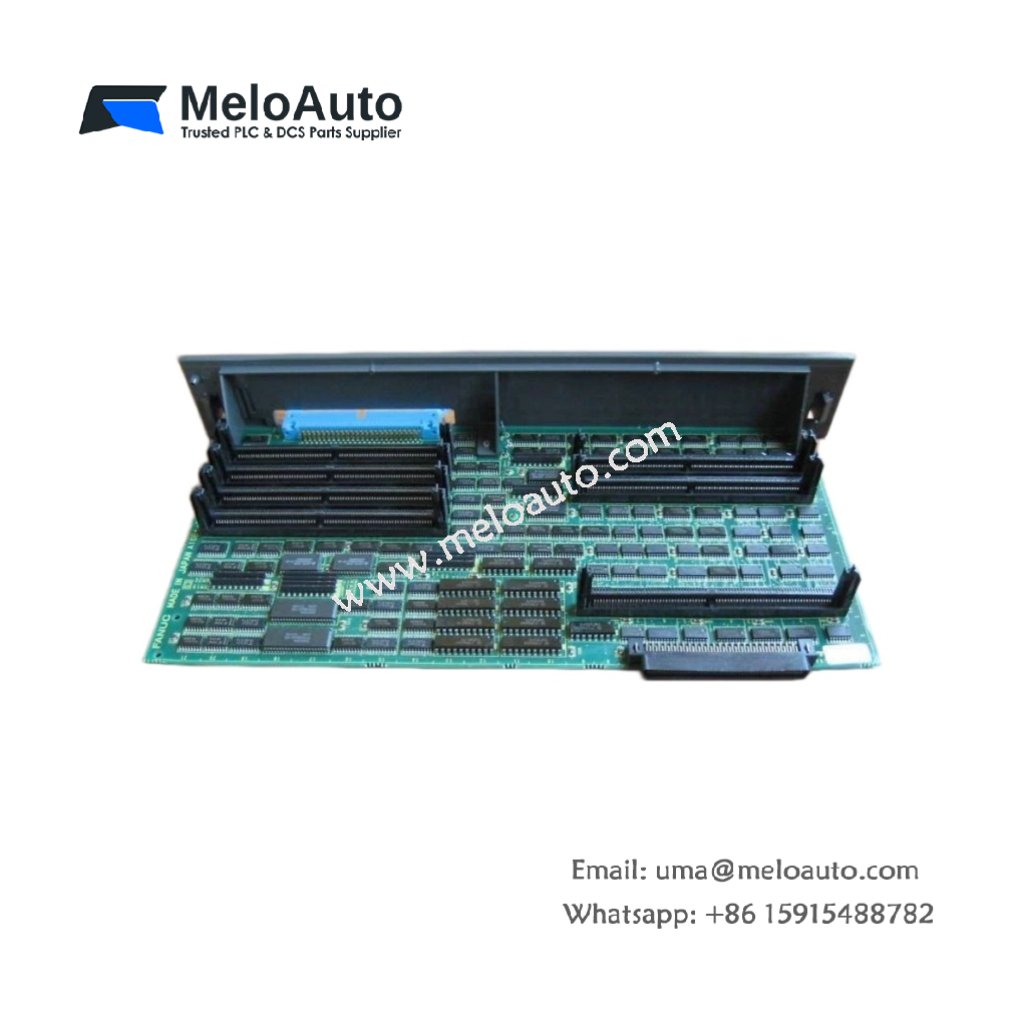
The GE A16B-2201-0800/03B processes vision and image data for GE Fanuc CNC applications. You can install this board into the main CNC rack of Series 15 or 16 controllers. It handles camera inputs and performs real-time image analysis. This PCB suits automated inspection and robotic guidance systems.
Technical Specifications and Hardware Layout
This vision engine PCB measures 260 mm in height. Its width reaches 210 mm, and the depth equals 35 mm. The GE A16B-2201-0800/03B weighs approximately 0.58 kilograms. A single multilayer PCB holds all processing and interface circuits. The board contains no energy storage capacitors or batteries. Two 34-pin ribbon connectors provide camera input interfaces. One 50-pin header handles vision output signals to the CNC. Four test points allow signal monitoring with oscilloscope probes.
| Parameter | Specification |
|---|---|
| Model | GE A16B-2201-0800/03B |
| Category | Vision Engine PCB |
| Dimensions (H x W x D) | 260 mm x 210 mm x 35 mm |
| Weight | 0.58 kg |
| PCB Layers | 8 |
| Energy Storage | None |
| Camera Connectors | 2 x 34-pin ribbon |
| CNC Interface | 1 x 50-pin header |
| Test Points | 4 |
| Temperature Range | 0°C to 55°C |
Processing Capabilities and Performance
The GE A16B-2201-0800/03B executes vision algorithms at 200 megapixels per second. It supports up to two industrial cameras simultaneously. This board performs pattern recognition and edge detection in real time. Consequently, it enables automated part inspection and tool monitoring. The engine includes 32 MB of dedicated image buffer memory. It communicates with the main CNC processor through a high-speed bus. The board generates pass/fail outputs for quality control decisions.
Installation and Diagnostic Features
You must insert this board firmly into a dedicated CNC rack slot. Transitioning to wiring, use shielded coaxial cables for camera connections. The board includes LED indicators for power and camera sync status. For troubleshooting, use the four test points with an oscilloscope. Always power off the system before removing or inserting the board. The operating temperature range spans from 0°C to 55°C reliably.


 and 24 VDC (5 A) outputs, ideal for industrial automation systems.")

 Analog I/O Module")


WeChat
Scan the QR Code with wechat