 MeloAuto-Trusted PLC & DCS Parts Supplier
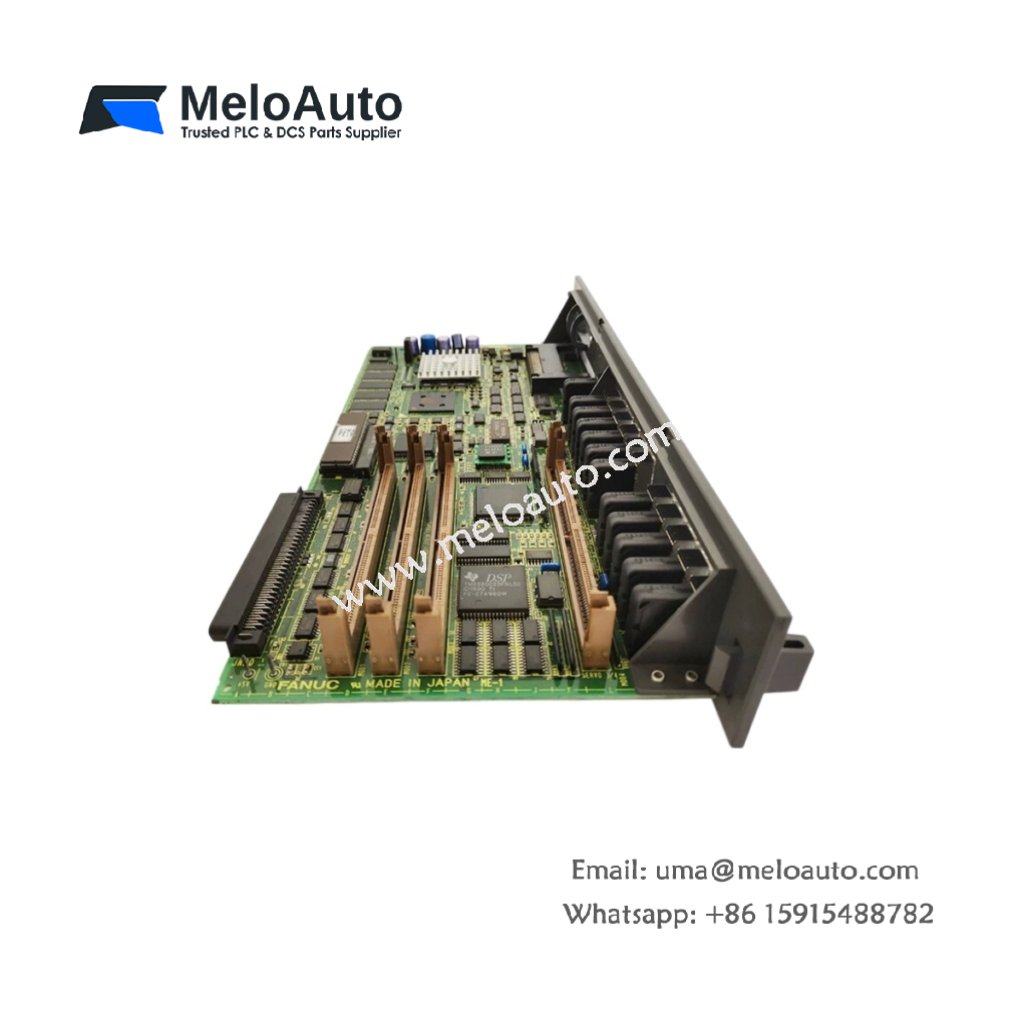
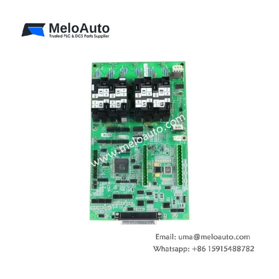
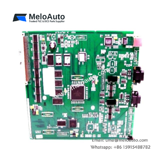
The A16B-2200-0471/12B functions as a printed circuit board for GE Fanuc CNC systems. This unit processes control signals for axis positioning and spindle management. It handles communication between the operator panel and servo drives. Therefore, this board provides essential control for precision machining applications.
Technical Specifications
We engineered this PC board for reliable operation in machine tool environments. Its multi-layer design ensures signal integrity across all data paths. Moreover, the board includes test points for easy field diagnostics.
| Parameter | Specification |
|---|---|
| Dimensions (H x W) | 10.5 x 7.8 inches (267 x 198 mm) |
| Weight | 0.54 kg (1.2 lbs) |
| Layer Count | 6-layer epoxy glass construction |
| Edge Connectors | 1x 96-pin DIN, 2x 50-pin ribbon headers |
| Test Points | 15 gold-plated diagnostic points |
| Mounting Holes | 4 corner mounting locations |
| Operating Temperature | 0°C to 55°C (32°F to 131°F) |
Circuit Architecture and Components
The A16B-2200-0471/12B contains multiple integrated circuits for logic processing. Surface-mount technology populates both sides of this board. Key components include EPROMs, RAM chips, and bus interface logic. Consequently, this PC board handles complex control tasks without external processing modules.
Memory Components and Data Retention
This PC board includes several EPROM devices for firmware storage. These EPROMs retain their data without any battery backup indefinitely. The board also contains RAM chips for temporary variable storage during operation. A lithium battery preserves this RAM data during power-off conditions. The battery provides backup for approximately 10,000 hours of cumulative downtime.
Connector Layout and Signal Interfaces
The A16B-2200-0471/12B uses a 96-pin DIN connector for backplane interface. Two 50-pin ribbon headers link to operator panel and servo modules. Each connector has keyed orientation to prevent incorrect installation. Fifteen gold-plated test points give you access to major signal lines for troubleshooting.
Power Consumption and Energy Storage
This PC board draws 1.2A from the 5V DC backplane supply. It also consumes 100 mA from the 24V DC field power source. The lithium battery serves as the only energy storage component onboard. This battery retains CMOS RAM settings during main power interruptions.
Installation and Handling Guidance
Mount the A16B-2200-0471/12B using four screws into the rack standoffs. Observe proper ESD precautions when handling this printed circuit board. Verify all ribbon cables latch securely before applying power. Check the lithium battery voltage during every preventive maintenance schedule.







WeChat
Scan the QR Code with wechat