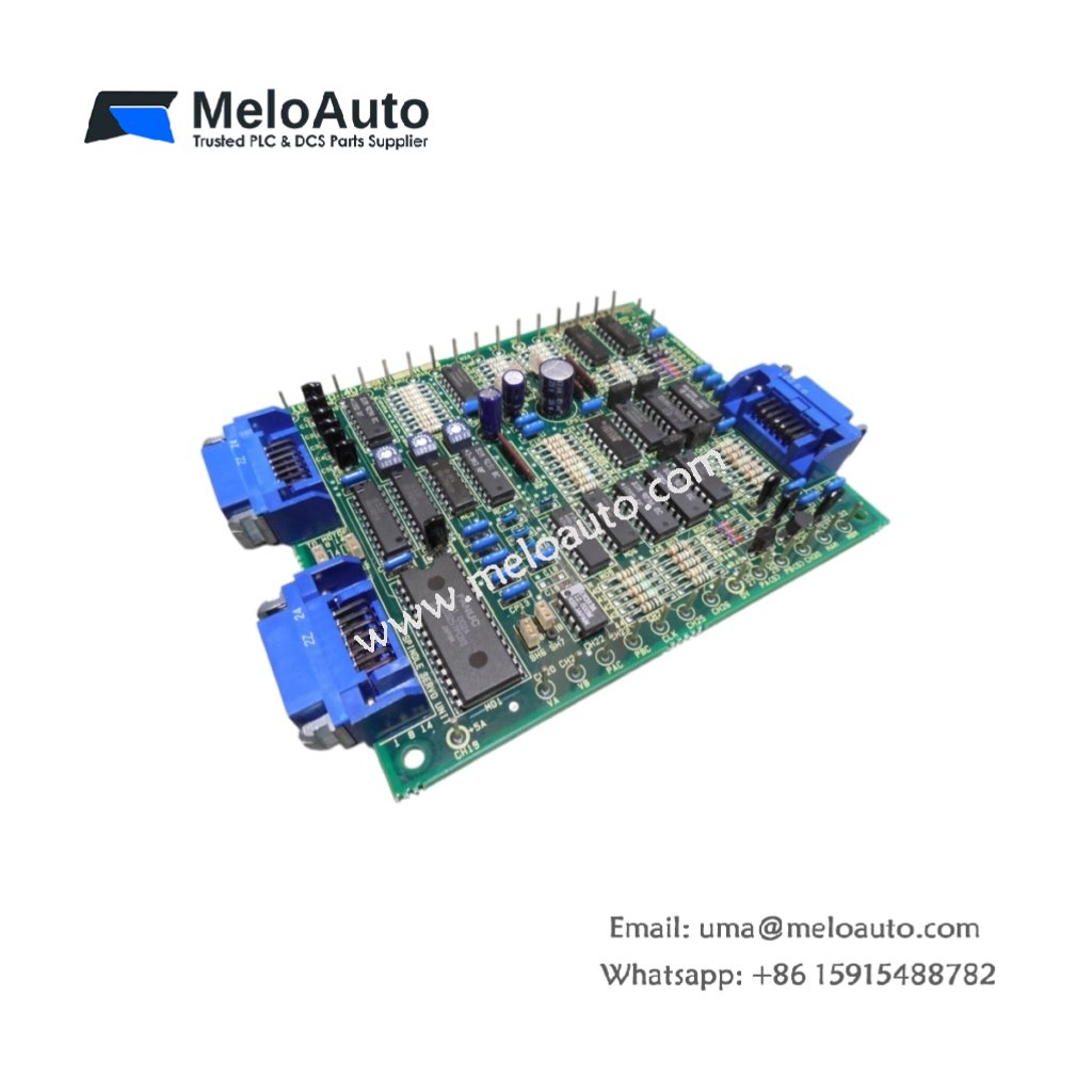
The GE A16B-1600-0440/06A controls spindle motor speed and torque in GE Fanuc CNC systems. You can install this board into the main drive rack of Series 15 or 16 controllers. It processes speed commands and feedback signals from the spindle encoder. This board suits machining centers, lathes, and high-speed milling applications.
Technical Specifications and Hardware Layout
This spindle drive board measures 260 mm in height. Its width reaches 210 mm, and the depth equals 35 mm. The GE A16B-1600-0440/06A weighs approximately 0.65 kilograms. A single multilayer PCB holds all motor control and interface circuits. The board contains no energy storage capacitors or batteries. One 34-pin ribbon connector handles encoder feedback signals. Two 50-pin headers provide command and status signals to the CNC. Six test points allow signal monitoring with oscilloscope probes.
| Parameter | Specification |
|---|---|
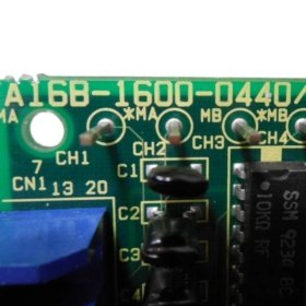
| Model | GE A16B-1600-0440/06A |
| Category | Spindle Drive Board |
| Dimensions (H x W x D) | 260 mm x 210 mm x 35 mm |
| Weight | 0.65 kg |
| PCB Layers | 6 |
| Energy Storage | None |
| Encoder Connector | 1 x 34-pin ribbon |
| CNC Interface | 2 x 50-pin headers |
| Test Points | 6 |
| Temperature Range | 0°C to 55°C |
Control Capabilities and Performance
The GE A16B-1600-0440/06A generates analog command voltages from -10 V to +10 V. It controls spindle speed from 0 to 10,000 RPM depending on the motor. This board reads encoder feedback at frequencies up to 1 MHz. Consequently, it supports rigid tapping and constant surface speed cutting. The board includes a built-in overspeed detection circuit for safety. It communicates with the CNC processor through a high-speed serial bus. The board generates fault signals for overload and overtemperature conditions.
Installation and Diagnostic Features
You must insert this board firmly into a dedicated CNC drive rack slot. Transitioning to wiring, route encoder cables away from motor power cables. The board includes LED indicators for power and enable status. For troubleshooting, use the six test points with an oscilloscope. Always power off the system before removing or inserting the board. The operating temperature range spans from 0°C to 55°C reliably.


 Analog I/O Module")


WeChat
Scan the QR Code with wechat