
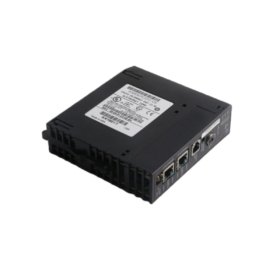
The GE A16B-1200-0450/02A functions as a control PCB for CNC systems. This circuit board manages signal routing and logic processing. You will find it inside main controller cabinets for machine tools. It interfaces with servo drives and I/O modules. Therefore, this board is essential for system coordination.
This board measures 260 mm in height and 200 mm in width. Its thickness reaches 18 mm including component height. The unit weighs approximately 0.65 kilograms. It contains seven major ICs and three programmable logic devices. Two large connectors provide the primary signal interfaces. Additionally, you get fifteen jumper settings for configuration.
Key Technical Specifications
| Parameter | Value |
|---|---|
| Manufacturer | GE Fanuc Automation |
| Model | A16B-1200-0450/02A |
| Product Type | Circuit Board / Control PCB |
| Board Dimensions | 260 x 200 mm |
| Thickness | 18 mm |
| Weight | 0.65 kg |
| Number of ICs | 7 major components |
| Programmable Devices | 3 (PLDs) |
| Connectors | 2 main + 4 auxiliary |
| Jumper Switches | 15 positions |
| Energy Storage | ≈ 120 µF (capacitive) |
| Layer Count | 4-layer PCB |
| Operating Voltage | 5 VDC and ±15 VDC |
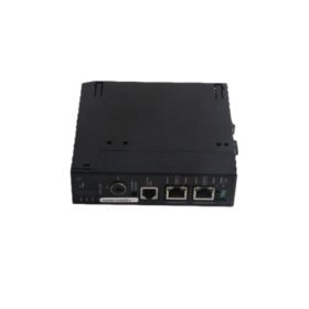
| Mounting Method | Chassis slide-in |
Internal Architecture and Components
The GE A16B-1200-0450/02A stores minimal energy in its filter capacitors. Small ceramic capacitors hold approximately 120 microfarads total. A large TL604 processor chip handles all logic functions. This processor runs at 12 MHz clock speed. Three programmable logic devices manage address decoding and timing. You also get eight LED indicators for status monitoring. These LEDs show power, run, and fault conditions clearly.
Connection Interfaces and Signal Flow
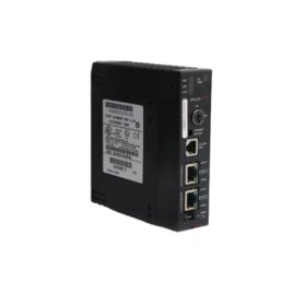
You will find two 50-pin ribbon cable headers on this board. One header carries input signals from remote modules. The other header delivers output commands to servo amplifiers. Four smaller pin headers support auxiliary functions like limit switches. Always align the ribbon cable red stripe with pin one. The GE A16B-1200-0450/02A uses a 4-layer PCB construction. Two inner layers provide power and ground planes. This design reduces electrical noise significantly.
Configuration and Installation Steps
You must set the fifteen jumper switches before installation. Each jumper selects an axis number or machine parameter. Refer to the original system manual for proper settings. Slide this board into a standard 16-slot backplane gently. Use both ejector tabs to seat it firmly. Then, secure the front panel with two screws. The board draws 1.2 amps from the 5 VDC supply. It also needs 0.2 amps from the ±15 VDC rails. Always power off the system before removing this unit.