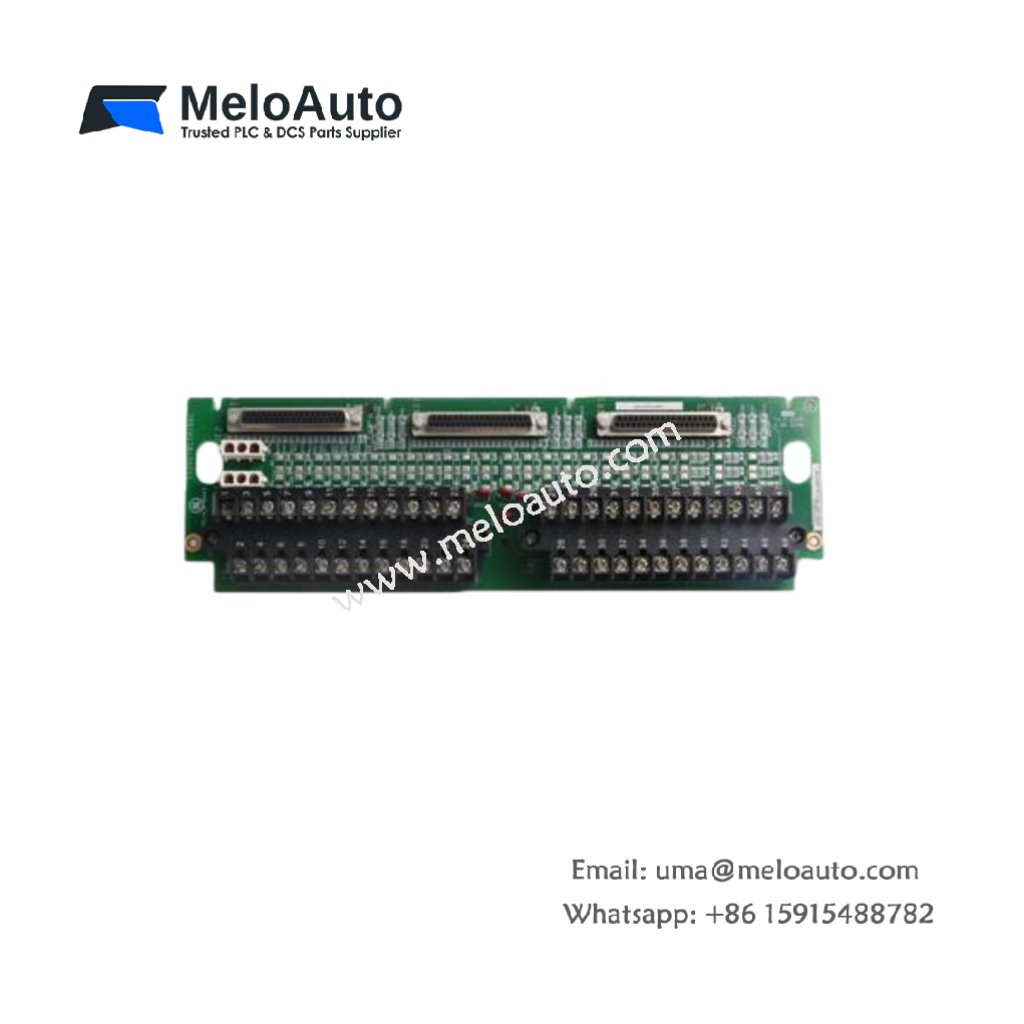
The GE VMIVME-2540-200000 provides high-resolution analog input for VMEbus systems. This module converts 16 differential analog signals into digital values. You will find it in data acquisition and process control applications. It delivers 16-bit resolution for precise measurement tasks. Therefore, this unit suits demanding industrial environments.
This module measures 160 mm in height and 100 mm in width. Its depth reaches 220 mm for standard 6U VME backplanes. The unit weighs approximately 0.48 kilograms. It contains one main 16-bit ADC converter chip. Four instrumentation amplifiers condition the incoming signals. Additionally, you get eight jumper blocks for input range selection.
Key Technical Specifications
| Parameter | Value |
|---|---|
| Manufacturer | GE Fanuc / VMIC |
| Model | VMIVME-2540-200000 |
| Product Type | Analog Input Module |
| Number of Channels | 16 differential |
| ADC Resolution | 16 bits |
| Input Voltage Ranges | ±10V, ±5V, 0-10V, 0-5V |
| Sampling Rate | 100 kHz (maximum) |
| Dimensions (H x W) | 160 x 100 mm |
| Depth | 220 mm |
| Weight | 0.48 kg |
| Number of Amplifiers | 4 (instrumentation) |
| Jumper Blocks | 8 positions |
| Energy Storage | ≈ 250 µF (capacitive) |
| Bus Interface | VMEbus P1/P2 connectors |
| Operating Temperature | 0°C to +55°C |
Internal Architecture and Energy Storage
The GE VMIVME-2540-200000 stores moderate energy in its analog filter section. Electrolytic capacitors hold approximately 250 microfarads of total capacitance. These capacitors smooth the power rails for stable conversion. A single 16-bit successive approximation ADC chip performs all conversions. This ADC completes one channel in just 10 microseconds. Four programmable gain amplifiers adjust input sensitivity automatically. You also get a built-in calibration reference voltage source.
Connection Interfaces and Signal Wiring
You will find a front-panel 37-pin D-sub connector on this module. This connector accepts all 16 differential analog input pairs. Use shielded twisted-pair cables for best noise immunity. Connect the cable shield to the module’s ground pin only. The GE VMIVME-2540-200000 also uses both P1 and P2 backplane connectors. P1 carries power and address lines from the VMEbus. P2 transfers the 16-bit digital conversion results.
Configuration and Installation Steps
You must set the eight jumper blocks before installation. Each jumper selects the voltage range for two adjacent channels. You can mix ranges across different channel pairs easily. Slide this 6U module into any standard VME slot gently. Push the injector/ejector handles to seat the backplane pins fully. Then, secure the front panel with two retaining screws. The module draws 450 mA from the +5 VDC supply. It also needs 100 mA from the ±12 VDC rails. Always configure the jumpers before powering the system.


 Analog I/O Module")


WeChat
Scan the QR Code with wechat