The Fuji NC1F-HC1 counts rapid pulse trains from encoders and sensors. This high speed counter module captures signals up to 100 kHz reliably. It connects directly to the NC1 series backplane for real‑time processing. Control engineers use this unit for precision position monitoring and flow measurement.
Complete Technical Specifications
| Parameter | Specification |
|---|---|
| Dimensions (W x H x D) | 82 mm x 90 mm x 55 mm |
| Weight | 0.26 kg |
| Number of Counter Channels | 2 independent channels |
| Maximum Input Frequency | 100 kHz per channel |
| Input Type | 24V DC (sink/source) or 5V differential |
| Counter Resolution | 32 bits |
| Counter Modes | Up, down, up/down, quadrature (x1, x2, x4) |
| Preset Value | 32 bits programmable |
| Comparator Outputs | 2 per channel |
| Internal Energy Storage | 100 µF capacitor |
| Operating Voltage | 5V DC from backplane |
| Power Consumption | 2 W typical |
| Input Protection | Optocoupler (24V) or direct (5V) |
| LED Indicators | Channel A, Channel B, Compare |
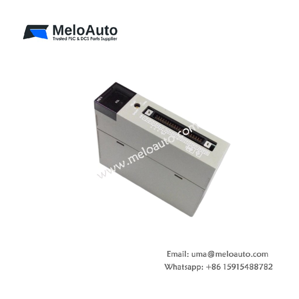
Physical Layout and Connection Points
The Fuji NC1F-HC1 weighs only 0.26 kilograms for lightweight mounting. Its 82 mm width occupies a single slot on the base board. Two independent counter channels accept different input types. A 20‑pin terminal block provides all field wiring connections. Each channel includes two status LEDs for signal activity. A 100 µF capacitor filters supply voltage fluctuations.
Counting Characteristics and Performance
Each channel accepts frequencies up to 100 kilohertz maximum. The module supports quadrature encoders with x1, x2, or x4 multiplication. Therefore, you can capture precise position data from linear scales. The 32‑bit counter rolls over after 4 billion pulses. Consequently, this unit handles long travel distances without resetting. Each channel includes programmable preset and comparator outputs.
Installation and Wiring Guidelines
Mount the Fuji NC1F-HC1 into any NC1 series base slot. First, disconnect system power completely before handling. Then select the input mode via configuration software. Wire 24V sensors using standard optocoupler protection. Wire 5V differential signals directly for higher noise immunity. Connect the comparator outputs to PLC inputs for event triggering. After wiring, apply power and set the counter mode. Finally, test with a known pulse generator.
System Integration and Application Notes
This counter module works with NC1 series CPUs and power supplies. Typical applications include cut‑to‑length machines and winding controls. The unit also suits flow meter totalization and conveyor tracking. For quadrature encoders, use the x4 mode for maximum resolution. The comparator outputs can trigger external devices at preset positions.


 Analog I/O Module")


WeChat
Scan the QR Code with wechat