 MeloAuto-Trusted PLC & DCS Parts Supplier
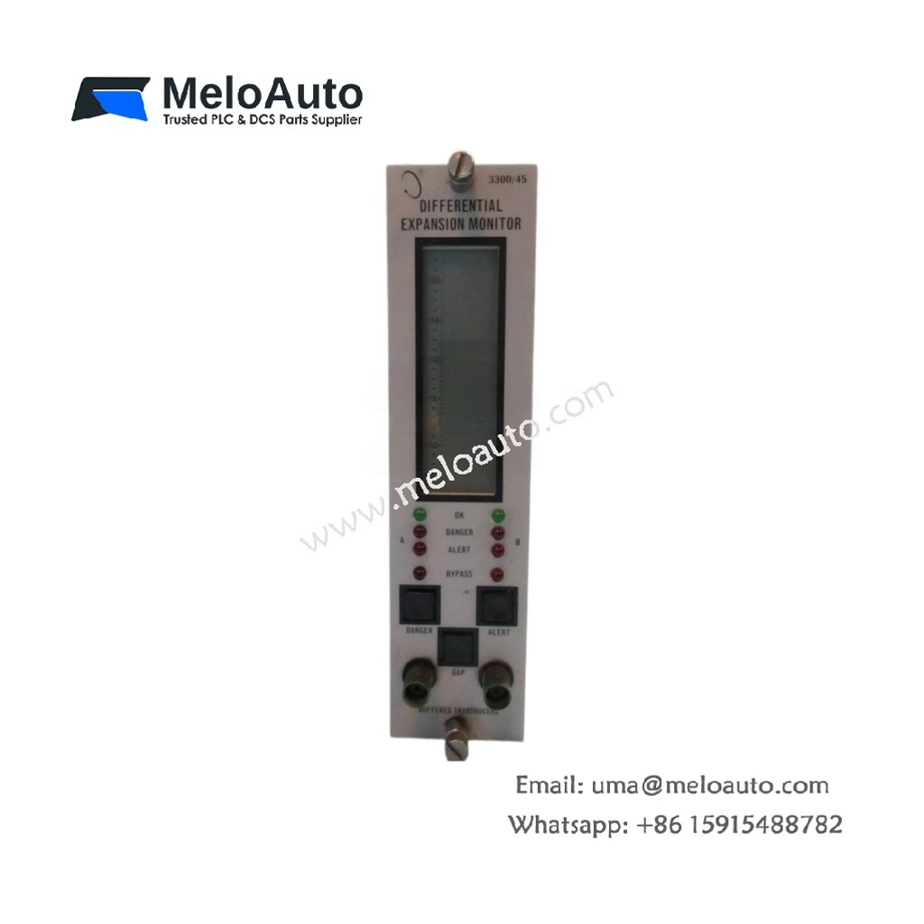
3300 Series Expansion Monitoring Module
The 3300/45-01-02-03-00 functions as an expansion module within the 3300 Series monitoring system. This device adds extra monitoring capabilities to an existing rack configuration. It accepts input from velocity transducers or accelerometers and processes the signals accordingly. The module then communicates its data to the main monitoring system via the backplane.
Key Technical Specifications
| Parameter | Specification |
|---|---|
| Model | 3300/45-01-02-03-00 |
| Series | 3300 Series |
| Function | Expansion monitoring module |
| Input Type | Accepts velocity or accelerometer transducer signals |
| Power Supply | Draws +24 Vdc from the chassis backplane |
| Outputs | Provides relay contacts plus buffered outputs |
| Frequency Response | Covers a range from 1.0 Hz to 10.0 kHz |
| Input Channels | Offers two independent input channels |
| Alarm Setpoints | Features individually configurable thresholds |
| Time Delay | Includes adjustable delay from 0.1 to 10.0 seconds |
| Operating Temperature | Functions from -20°C to +65°C |
| Storage Temperature | Withstands -40°C to +85°C |
| Dimensions | Measures 241.3 mm x 25.4 mm x 152.4 mm |
| Weight | Weighs approximately 1.2 kg |
| Mounting | Plugs into standard 3300 Series rack slots |
| Termination | Uses pluggable screw terminal blocks |
| LED Status | Displays OK, ALERT, and DANGER indicators |
Expansion Capabilities and Signal Processing
This module extends the channel capacity of an existing 3300 Series system. It processes each input independently and compares the signals against user-defined limits. The device then triggers the appropriate relays when a channel exceeds its threshold. Moreover, it provides a buffered output for each channel to support external analysis. The module integrates seamlessly with the main rack’s backplane for data exchange.
Installation and Configuration
First, insert the 3300/45-01-02-03-00 into an available slot within the chassis. Ensure the module locks firmly into position before connecting any cables. Next, wire the transducer inputs to the designated terminal blocks. After that, apply power and observe the LED indicators for normal operation. You can then set the alarm thresholds using the front-panel adjustment controls.
Maintenance and Operational Reliability
This module stores its configuration data in non-volatile memory. Therefore, you will not lose your settings during a power outage. We recommend you test each channel periodically with a calibrated signal source. You should also examine the terminal connections for tightness during routine inspections.





WeChat
Scan the QR Code with wechat