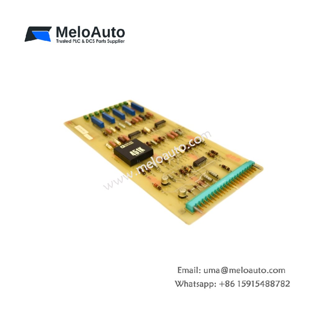
This PC board processes control and feedback signals in GE drive systems. It manages communication between the main controller and power electronics. The unit mounts inside the drive cabinet for reliable operation.
Technical specifications
| Parameter | Specification |
|---|---|
| Brand | GE (General Electric) |
| Model | GE 4176J86-G01 |
| Category | PC Board (Printed Circuit Board) |
| PCB Layer Count | 4 layers |
| Base Material | FR-4 flame retardant |
| Component Count | Approximately 105 components |
| Integrated Circuits | 12 ICs (logic, op-amps, drivers) |
| Connector Types | 2 x 30-pin headers, 1 x 16-pin ribbon |
| Test Points | 7 gold-plated test points |
| Potentiometers | 2 trim pots (calibration) |
| Power Supply | 24V DC external |
| Current Consumption | 140 mA typical |
| Fuse Protection | 1 x 1.25A slow-blow fuse |
| Status Indicators | 2 x LEDs (Power, Run) |
| Dimensions (L x W) | Approx. 18 cm x 13 cm |
| Thickness | Approx. 1.6 mm |
| Weight | Approx. 0.25 kg |
| Energy Storage | 6 x electrolytic capacitors (150 µF each) |
| Operating Temperature | 0°C to 55°C |
| Mounting | 4 x screw holes (M3) |
Detailed Technical Analysis
This PC board uses a 4-layer FR-4 design for signal integrity. The inner layers provide power distribution and ground shielding. Approximately 105 discrete components populate both sides of the board. These include resistors, capacitors, diodes, and twelve integrated circuits.
Now let us examine its energy storage features. The GE 4176J86-G01 contains six electrolytic capacitors. Each capacitor stores 150 microfarads of electrical charge. These capacitors filter the 24V DC power input thoroughly. They also provide local energy for ICs during switching.
The board includes two trim potentiometers for field calibration. You can adjust these pots to fine-tune analog signal levels. The GE 4176J86-G01 features seven gold-plated test points for diagnostics. A 1.25-amp slow-blow fuse protects the board from overcurrent. Two LEDs provide visual status for power and run conditions.
Installation and Connection Guidelines
You mount this board using four M3 screws with insulating standoffs. Connect the 24V DC power supply to the designated terminal block. The board draws approximately 140 milliamps during normal operation. Always power down the drive before inserting or removing this board.
The GE 4176J86-G01 connects to other system boards via ribbon cables. Two 30-pin headers carry digital control signals and feedback. Match the cable orientation carefully to avoid pin damage. Verify all connections before applying power to the system.
Practical Applications
Engineers use this PC board for drive repair and system refurbishment. It serves as a direct replacement for failed original boards. The GE 4176J86-G01 also works in legacy drive upgrade projects. Its robust design suits industrial motor control applications.
Summary
To conclude, this PC board features 4-layer construction and 105 components. It weighs 0.25 kilograms and contains six filter capacitors. Choose GE 4176J86-G01 for reliable drive control board replacement.


 Analog I/O Module")


WeChat
Scan the QR Code with wechat