 MeloAuto-Trusted PLC & DCS Parts Supplier
Product Overview
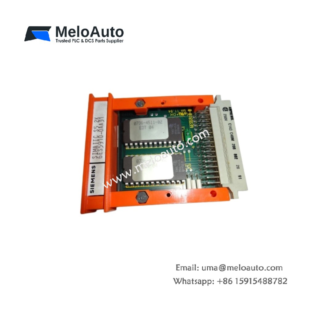
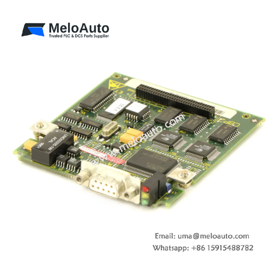
This interface module connects the S7-400 CPU to remote I/O stations via PROFIBUS DP. It supports a maximum transmission rate of 12 Mbps for efficient process data exchange. The module includes a 9-pin D-sub connector for direct PROFIBUS cable attachment. It measures 25 mm in width, 290 mm in height, and 210 mm in depth. The unit weighs approximately 600 grams for secure rack mounting. You can install this module in any available S7-400 slot.
This interface module manages up to 32 connected slave devices per PROFIBUS segment. It provides electrical isolation of 500 V DC between the bus and internal logic. The module automatically detects the baud rate during the startup phase. Its integrated termination resistors are switchable for the last station in a segment. The device supports both S7 and DP communication protocols.
Technical Specifications
| Parameter | Specification |
|---|---|
| Product Type | PROFIBUS DP Interface Module |
| Model | 6ES7963-1AA10-0AA0 |
| Communication Protocol | PROFIBUS DP |
| Transmission Rate | 9.6 kbps to 12 Mbps (auto) |
| Bus Connector | 9-pin D-sub female |
| Max Slaves per Segment | 32 |
| Electrical Isolation | Yes (500 V DC) |
| Supply Voltage | 5 V DC (from backplane) |
| Current Consumption | Typ. 200 mA |
| Power Loss | Typ. 1.0 W |
| Termination Resistors | Switchable (integrated) |
| Dimensions (W x H x D) | 25 mm x 290 mm x 210 mm |
| Weight | Approx. 600 g |
| Compatibility | S7-400 CPU (all models) |
| Operating Temperature | 0 °C to 60 °C |
Key Features and Benefits
This module seamlessly extends the S7-400’s I/O capacity across large distances. Its automatic baud rate detection simplifies the commissioning process significantly. The integrated termination eliminates the need for external bus terminators. You can replace this module without shutting down the entire rack system. The device supports time stamping for fault-tolerant process monitoring applications.
Installation and Configuration
You insert the module into a free slot on the S7-400 rack backplane. Tighten the retaining screws to secure the module firmly in position. Connect the PROFIBUS cable to the 9-pin D-sub connector on the front panel. You then configure the module’s parameters through the STEP 7 hardware configuration tool. Set the station address using the DIP switches on the module’s side panel. The CPU will establish communication with the slave devices after startup.
Typical Applications
Large manufacturing plants use this module to connect field devices to a central S7-400. Chemical facilities rely on it for distributing I/O across multiple process areas. The module also serves in water treatment and power generation applications.





WeChat
Scan the QR Code with wechat