


Core Function of This Solid State I/O Module
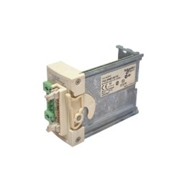
The Schneider TSXDMZ16DTK combines both inputs and outputs in a single compact module. This solid state I/O module provides 8 digital inputs and 8 digital outputs. It reads sensor signals and controls actuators without mechanical relays. Consequently, the unit saves valuable rack space in Modicon PLC systems.
Physical Dimensions and Module Construction
This solid state I/O module measures 130 mm in total height. Its width reaches 40 mm for a single-slot form factor. The module depth stands at 110 mm including the front connector. You will find 178 discrete components on this double-sided PCB. These include optocouplers, transistors, and transient suppression diodes. The Schneider TSXDMZ16DTK weighs approximately 230 grams for secure mounting.
Input Channels and Electrical Ratings
The Schneider TSXDMZ16DTK offers 8 sinking input channels on the top section. Each input accepts 24 V DC from proximity switches and push buttons. The input voltage range spans from 10 to 30 V DC continuously. Each channel draws 6 mA of current at 24 V DC nominal. Logic high detection occurs above 15 V DC. Logic low detection occurs below 5 V DC.
Output Channels and Drive Capability
This solid state I/O module provides 8 sourcing output channels on the bottom section. Each output uses a MOSFET transistor for silent, fast switching. The outputs deliver 24 V DC at 500 mA per channel maximum. Short-circuit protection limits current to 700 mA per output. A built-in flyback diode protects each output from inductive load spikes. The total output current across all channels reaches 4 A maximum.
Response Times and Switching Performance
The Schneider TSXDMZ16DTK achieves a typical input response time of 1 millisecond. Output turn-on delay reaches 0.2 milliseconds for fast applications. Output turn-off delay stays below 0.5 milliseconds for inductive loads. The module supports PWM operation up to 1 kHz frequency. These fast response times suit high-speed packaging and assembly machines.
Optical Isolation and Noise Immunity
This solid state I/O module provides 1,500 V RMS isolation between field and logic sides. Optocouplers separate each input and output channel group. The module includes RC filters for high-frequency noise rejection on inputs. Outputs feature transient voltage suppressors for load dump protection. Common mode rejection reaches 50 V per microsecond for reliable operation.
Status Indicators and Diagnostic Features
The Schneider TSXDMZ16DTK provides 16 LED status indicators. Eight green LEDs show the real-time status of each input channel. Eight red LEDs indicate which output channels are currently active. A single green LED confirms that the module has power. The front panel includes a label area for user-defined channel identification. All LEDs remain visible when the module locks into the rack.
Connector Type and Wiring Details
This solid state I/O module uses a 20-pin screw terminal block on the front. The terminal block is removable for easy wiring replacement. Each terminal accepts wire gauges from 0.2 to 1.5 mm². The module connects to the backplane via a 48-pin DIN 41612 connector. Gold-plated contacts ensure reliable connections in industrial environments.
Energy Storage and Power Requirements
The Schneider TSXDMZ16DTK draws 90 mA from a 5 V DC logic supply. It also requires 40 mA from a separate 24 V DC field supply at idle. Full output load adds up to 4 A to the field supply demand. The board incorporates four 47 µF tantalum capacitors for power filtering. Total stored energy reaches approximately 0.04 joules at nominal voltage.
| Parameter | Specification |
|---|---|
| Model | TSXDMZ16DTK |
| Brand | Schneider Electric |
| Category | Solid State I/O Module |
| Height x Width x Depth | 130 x 40 x 110 mm |
| Weight | 230 grams |
| Component Count | 178 |
| Input channels | 8 sinking |
| Input voltage range | 10 to 30 V DC |
| Input current | 6 mA per channel at 24 V |
| Logic high threshold | >15 V DC |
| Logic low threshold | <5 V DC |
| Output channels | 8 sourcing |
| Output technology | MOSFET transistor |
| Output voltage | 24 V DC |
| Output current | 500 mA per channel |
| Total output current | 4 A maximum |
| Short-circuit protection | 700 mA trip per output |
| Flyback diodes | Yes (per output) |
| Input response time | 1 ms typical |
| Output turn-on time | 0.2 ms |
| Output turn-off time | 0.5 ms (inductive) |
| PWM frequency support | Up to 1 kHz |
| Isolation voltage | 1,500 V RMS |
| CMRR | 50 V/µs |
| Status LEDs | 16 (8 green, 8 red) |
| Power LED | 1 green |
| Field connector | 20-pin removable screw terminal |
| Backplane connector | 48-pin DIN 41612 |
| Logic supply | 90 mA at 5 V DC |
| Field supply (idle) | 40 mA at 24 V DC |
| Filter capacitors | 4 x 47 µF tantalum |
| Total stored energy | 0.04 Joules |
| Wire gauge range | 0.2 to 1.5 mm² |
| Operating temperature | 0°C to +55°C |
Installation and Compatibility Notes
You must install this module in a Modicon TSX Premium PLC rack. Always remove the terminal block before inserting or extracting the module. Then, connect the 24 V field supply to the dedicated power terminals. The module requires configuration through Unity Pro or PL7 Pro software. Regular inspection of terminal screws prevents intermittent signal loss over time.


 Analog I/O Module")


WeChat
Scan the QR Code with wechat