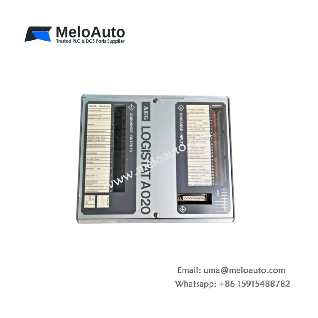
Core Function of This Control Unit
The Schneider LOGISTAT P020 executes sequential logic for small automation systems. This control unit replaces multiple timing relays and counters with a single device. It handles basic machine control without requiring a full PLC programming environment. Consequently, the module provides an economical solution for simple automation tasks.
Physical Dimensions and Enclosure Design
This control unit measures 105 mm in total height. Its width reaches 70 mm for a compact DIN rail footprint. The unit depth stands at 60 mm including the terminal blocks. You will find a molded thermoplastic housing with an IP20 protection rating. The Schneider LOGISTAT P020 weighs approximately 0.25 kilograms for panel mounting.
Logic Capacity and Program Storage
The Schneider LOGISTAT P020 stores up to 40 logic steps in its internal memory. This control unit executes Boolean logic functions including AND, OR, and NOT operations. It also provides 8 timer functions with adjustable time ranges from 0 to 99 minutes. The unit includes 8 counter functions for part counting applications. A non-volatile EEPROM retains the program without any battery backup.
Integrated I/O Channels and Ratings
This control unit provides 8 digital input channels built into the housing. It also includes 4 digital output channels for direct load control. The inputs accept 24 V DC from push buttons and limit switches. Each input draws 5 mA at 24 V DC for low power consumption. The outputs are relay type rated at 3 A at 250 V AC.
Input Adjustments and Configuration
The Schneider LOGISTAT P020 features a front panel with 12 adjustment potentiometers. Users set timer delays and counter preset values directly on the unit. Each potentiometer provides a range from 0 to 100 percent of full scale. A 4-position DIP switch selects operating modes and logic configurations. The unit requires no computer or software for programming changes.
Output Relay Specifications
This control unit uses four single-pole double-throw output relays. Each relay contact handles resistive loads up to 3 A at 250 V AC. Inductive loads require external snubber circuits for contact protection. The relays operate with a minimum switching load of 10 mA at 5 V. Mechanical relay life reaches 10 million cycles with no load. Electrical life reaches 100,000 cycles at full rated current.
Power Supply and Input Voltage
The Schneider LOGISTAT P020 accepts 24 V DC power from a field supply. Input voltage range spans from 20 to 30 V DC continuously. The unit draws 100 mA at 24 V DC with all outputs off. Full load adds up to 0.5 A across all four relay outputs combined. Reverse polarity protection prevents damage from incorrect wiring connections.
Status Indicators and Diagnostic Features
This control unit provides 15 LED status indicators. A green power LED illuminates when the unit receives 24 V DC. Eight green LEDs show the real-time status of each input channel. Four red LEDs indicate which output relays are currently energized. A yellow run LED flashes during normal program execution. A red fault LED signals internal hardware errors.
Energy Storage and Hold-Up Time
The Schneider LOGISTAT P020 incorporates two 100 µF electrolytic capacitors for power filtering. These capacitors provide 10 milliseconds of hold-up time during power dips. Total stored energy reaches approximately 0.03 joules at nominal voltage. The capacitors do not retain the program after power loss. The EEPROM stores the logic permanently without energy storage.
| Parameter | Specification |
|---|---|
| Model | LOGISTAT P020 |
| Brand | Schneider Electric |
| Category | Control Unit |
| Height x Width x Depth | 105 x 70 x 60 mm |
| Weight | 0.25 kg |
| Enclosure material | Thermoplastic, IP20 |
| Logic steps | 40 maximum |
| Timer functions | 8 (0 to 99 minutes) |
| Counter functions | 8 |
| Logic functions | AND, OR, NOT |
| Program storage | EEPROM (no battery) |
| Input channels | 8 digital, 24 V DC |
| Input current | 5 mA per channel |
| Output channels | 4 relay, SPDT |
| Output contact rating | 3 A at 250 V AC |
| Mechanical relay life | 10 million cycles |
| Electrical relay life | 100,000 cycles at full load |
| Adjustment potentiometers | 12 (front panel) |
| Configuration DIP switch | 4-position |
| Power supply input | 24 V DC (20-30 V range) |
| Unit current draw | 100 mA at 24 V DC |
| Total output current | 0.5 A maximum |
| Reverse polarity protection | Yes |
| Status LEDs | 15 (power, run, fault, I/O) |
| Filter capacitors | 2 x 100 µF |
| Stored energy | 0.03 Joules |
| Hold-up time | 10 ms |
| Operating temperature | 0°C to +50°C |
Installation and Programming Notes
You must mount this control unit on a standard 35 mm DIN rail. Always connect a fuse in series with the 24 V DC supply line. Then, set the DIP switch and potentiometers according to your application. The unit requires no computer software for configuration or testing. Regular verification of output relay contacts prevents unexpected failures over time.


 offers precise signal amplification, seamless integration, and high reliability for industrial automation systems.")


 Analog I/O Module")


WeChat
Scan the QR Code with wechat