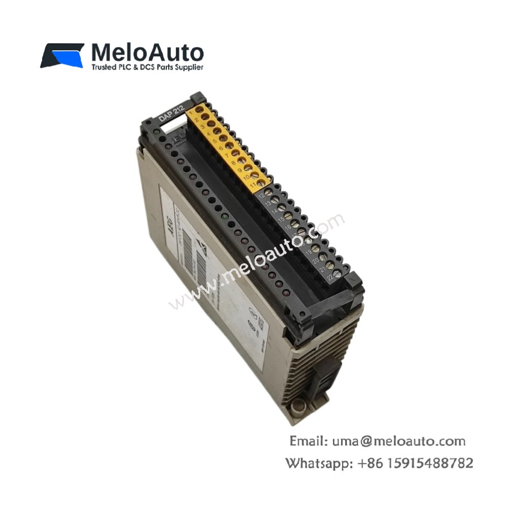
The Schneider DAP 212 combines 8 digital inputs and 4 digital outputs in one AEG-compatible module. This compact I/O unit interfaces field devices with legacy control systems. Therefore, it serves as a cost-effective solution for plant expansions and spare replacements.
Product Overview
We engineered this module for reliable signal conditioning in industrial environments. Its dedicated design matches the original AEG Modicon PLC architecture. Moreover, this unit provides optically isolated channels for noise immunity.
Technical Specifications
| Parameter | Specification |
|---|---|
| Dimensions | 12.0 cm (height) x 8.0 cm (width) x 9.0 cm (depth) |
| Weight | 0.35 kg (approximately 0.77 lb) |
| Interface Type | Single 20-pin backplane plus removable terminal block |
| Component Count | 86 components including optocouplers and filter circuits |
| Energy Storage | 6 ceramic capacitors (0.1 µF) plus 2 tantalum (10 µF) |
| Digital Inputs | 8 channels, 24V DC sink/source |
| Input Current | 7 mA typical per channel at 24V |
| Input Response | 8 ms standard filtering |
| Digital Outputs | 4 channels, relay type, Form A contacts |
| Output Rating | 2A at 30V DC, 1A at 250V AC |
| Output Response | 10 ms typical for relay closure |
| Isolation | 1500V RMS between field and logic |
Input Circuit Design
The Schneider DAP 212 uses optocoupler isolation on all eight input channels. Its six ceramic capacitors filter high-frequency noise from the field wiring. Additionally, two tantalum capacitors smooth the internal logic power supply. You get clean signal detection even with long cable runs near drives.
Energy Storage Function
Six ceramic capacitors decouple noise from each input optocoupler. Two tantalum capacitors provide local energy storage for the relay coils. When an output relay energizes, these capacitors supply the inrush current. This design prevents voltage dips on the backplane power supply. Consequently, other modules in the rack continue operating without interruption.
Installation Steps
Insert this I/O module into any AEG-compatible rack slot in the system. Align the Schneider DAP 212 with the backplane guide rails carefully. Push the module forward until its locking tab clicks into position. Then tighten the top and bottom retaining screws for secure mounting. Connect field wiring to the removable front terminal block.
Input Wiring Configuration
Terminals 1 through 8 accept 24V DC signals from sensors and switches. Terminal 9 provides the common return for all input channels. Each input draws 7 mA at 24V, well below the sensor’s output capability. The module accepts both sinking and sourcing wiring arrangements. For sinking inputs, connect sensor output to terminal and common to +24V. For sourcing inputs, reverse the connections accordingly.
Output Wiring Configuration
Terminals 10 through 13 connect to the four relay output coils. Terminal 14 provides the common connection for all four relays. Each relay switches both AC and DC loads up to its rated values. Use an external snubber for inductive loads like small motors or solenoids. The relays are not protected against short circuits or overloads externally.
Status Indication
Eight green LEDs indicate the state of each input channel. Four yellow LEDs show when each output relay energizes. A single green power LED illuminates when the backplane supply is present. All LEDs remain visible with the module installed in a closed cabinet. The relay output LEDs also indicate the coil status, not contact position.
Replacement Information
This module replaces original AEG DAP 212 units in existing PLC racks. Many cement and mining plants use the Schneider DAP 212 for legacy system support. Its robust design accepts wide ambient temperatures from 0°C to 60°C.


 Analog I/O Module")


WeChat
Scan the QR Code with wechat