Core Function of This Series Module
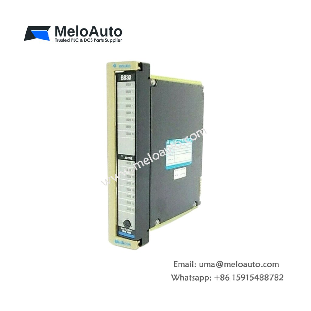
The Schneider ASB832016 provides 16 digital output channels for Advantys STB systems. This series module controls actuators, solenoids, and indicator lamps directly. It delivers 24 V DC outputs with short-circuit and overload protection. Consequently, the module enables reliable machine control in distributed I/O architectures.
Physical Dimensions and Module Construction
This series module measures 112 mm in total height. Its width reaches 30 mm for a compact Advantys STB form factor. The module depth stands at 85 mm including the terminal block. You will find 168 discrete components on this double-sided PCB. These include MOSFET arrays, optocouplers, and transient suppression diodes. The Schneider ASB832016 weighs approximately 155 grams for DIN rail mounting.
Output Channels and Electrical Ratings
The Schneider ASB832016 offers 16 sourcing output channels in two isolated groups. Group A covers channels 1 through 8 with a common return. Group B covers channels 9 through 16 with a separate common return. Each output uses a MOSFET transistor for silent, fast switching. The outputs deliver 24 V DC at 0.3 A per channel maximum. Short-circuit protection limits current to 0.5 A per output channel.
Switching Performance and Response Times
This series module achieves a typical turn-on delay of 0.15 milliseconds. Turn-off delay reaches 0.35 milliseconds for inductive loads. The module supports PWM operation up to 500 Hz frequency. Each output channel features a dedicated status LED for visual feedback. These fast response times suit high-speed pick-and-place and packaging machines.
Output Protection and Diagnostic Features
The Schneider ASB832016 includes comprehensive protection circuits per channel. Overcurrent protection limits each channel to safe operating levels. Short-circuit detection shuts down the affected output within microseconds. Overtemperature protection reduces current if the module exceeds safe limits. A red LED indicates a short-circuit or overcurrent condition per channel group.
Bus Interface and Communication
This series module connects to the Advantys STB island bus via a 10-pin ribbon cable. The module receives output data from the fieldbus master cyclically. It requires no user configuration for basic output operation. The module supports hot-swapping for maintenance without system shutdown. An amber LED indicates active communication with the bus master.
Status Indicators and Visual Feedback
The Schneider ASB832016 provides 19 LED status indicators. Sixteen green LEDs show the real-time status of each output channel. A green module power LED illuminates when the unit receives 24 V DC. A red group fault LED signals short-circuit conditions for Group A. Another red group fault LED signals faults for Group B. The front panel includes a label area for user-defined channel identification.
Connector Type and Wiring Details
This series module uses a 20-pin spring clamp terminal block. The terminal block is removable for easy wiring replacement. Each terminal accepts wire gauges from 0.2 to 1.5 mm². The module includes a 4-pin power connector for the 24 V field supply per group. Gold-plated contacts ensure reliable connections in industrial environments.
Energy Storage and Power Requirements
The Schneider ASB832016 draws 60 mA from a 5 V DC logic supply. It also requires 30 mA from a 24 V DC field supply at idle. Full output load adds up to 4.8 A to the field supply demand. The board incorporates four 47 µF electrolytic capacitors for power filtering. Total stored energy reaches approximately 0.03 joules at nominal voltage.
| Parameter | Specification |
|---|---|
| Model | ASB832016 |
| Brand | Schneider Electric |
| Category | Series Module / Output Module |
| Height x Width x Depth | 112 x 30 x 85 mm |
| Weight | 155 grams |
| Component Count | 168 |
| Output channels | 16 sourcing |
| Isolation groups | 2 (8 channels each) |
| Output technology | MOSFET transistor |
| Output voltage | 24 V DC |
| Output current | 0.3 A per channel |
| Short-circuit protection | 0.5 A trip per channel |
| Overtemperature protection | Yes (current reduction) |
| Flyback diodes | Yes (per output) |
| Turn-on delay | 0.15 ms typical |
| Turn-off delay | 0.35 ms (inductive) |
| PWM frequency support | Up to 500 Hz |
| Status LEDs | 16 green (outputs) |
| Power LED | 1 green |
| Fault LEDs | 2 red (short-circuit per group) |
| Bus LED | 1 amber (communication) |
| Field connector | 20-pin spring clamp (removable) |
| Power connectors | 2 x 4-pin (24 V per group) |
| Bus connector | 10-pin ribbon cable |
| Logic supply | 60 mA at 5 V DC |
| Field supply (idle) | 30 mA at 24 V DC |
| Field supply (full load) | 4.83 A at 24 V DC |
| Filter capacitors | 4 x 47 µF |
| Total stored energy | 0.03 Joules |
| Hot-swap support | Yes |
| Wire gauge range | 0.2 to 1.5 mm² |
| Operating temperature | 0°C to +55°C |
Installation and Compatibility Notes
You must mount this module on a DIN rail within an Advantys STB island. Always remove the terminal block before inserting or extracting the module. Then, connect the 24 V field supply to both group power connectors. The module automatically configures itself from the bus master data. Regular inspection of spring clamp terminals prevents intermittent connection failures over time.


, 20-pin connectors, foil shield, PVC jacket")


 Analog I/O Module")


WeChat
Scan the QR Code with wechat