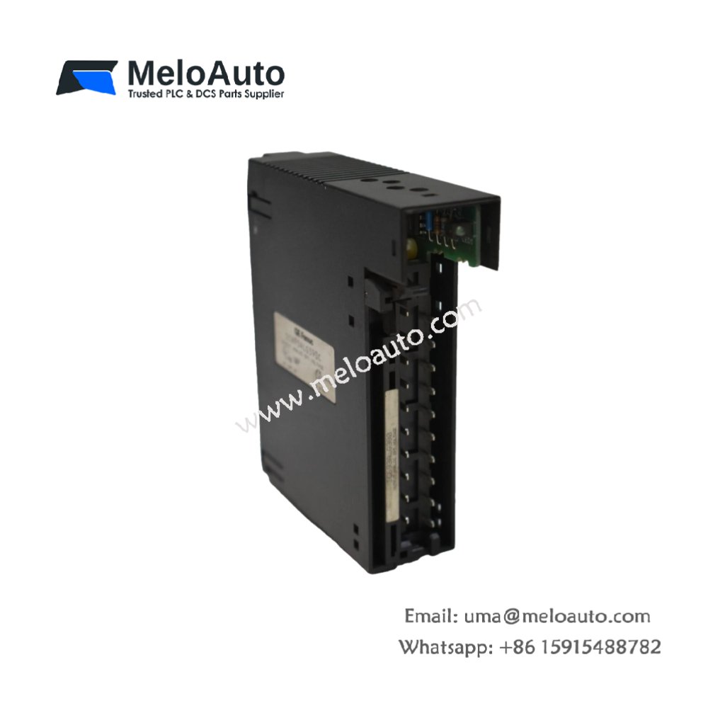
This analog output module converts digital values into proportional voltage or current signals. It controls actuators, valves, and drives in a Series 90-30 system. You will install this module in any I/O slot of the main rack.
Key Technical Specifications
The IC693ALG390C provides four analog output channels with 12-bit resolution. Each channel operates as either voltage or current output. The module also includes individual channel configuration for flexible field applications.
| Parameter | Technical Data |
|---|---|
| Product Type | Series 90-30 Analog Output Module |
| Output Channels | 4 (individually configurable) |
| Output Ranges | 0-10V, ±10V, 4-20 mA (selectable) |
| Resolution | 12 bits (4096 counts) |
| Settling Time | 5 ms to 1 LSB typical |
| Accuracy | ±0.25% of full scale at 25°C |
| Output Load (Voltage) | 2 kΩ minimum |
| Output Load (Current) | 0-600 Ω maximum |
| Dimensions (W x H x D) | 2.5 cm x 13.6 cm x 12.7 cm |
| Total Weight | 0.28 kg (0.62 lbs) |
| Terminal Block | 1 x 20-position removable |
| Backplane Connector | 24-pin Series 90-30 interface |
| Onboard Resistors | 36 precision resistors |
| Onboard Capacitors | 18 filtering capacitors |
| Energy Storage | 220 µF decoupling capacitance |
| Operating Temperature | 0°C to 60°C |
Hardware Architecture and Signal Conversion
The IC693ALG390C uses a 12-bit digital-to-analog converter for each output channel. Thirty-six precision resistors set gain and offset for all four channels. Eighteen filtering capacitors remove ripple from each analog output. The module also includes a voltage reference with ±0.1% stability.
Interface and Connectivity
One 20-position removable terminal block connects analog wiring to field devices. Each output channel includes dedicated positive and common terminals. A 24-pin backplane interface receives digital values from the CPU. The module requires an external 24V DC supply for the analog circuits.
Practical Installation Notes
Install this output module in any I/O slot of a Series 90-30 rack. The IC693ALG390C needs DIP switch configuration for range selection. Always use shielded twisted-pair cable for 4-20 mA current loops. Verify the load impedance matches the selected output range for proper operation.


 Analog I/O Module")


WeChat
Scan the QR Code with wechat