Why This Drive Control Board Ensures Stable Turbine Operation
The GE DS200SDCCG4A DS200SDCCG4AFD manages exciter and drive functions in Mark V turbines. This board integrates three 16‑bit microprocessors for parallel data processing. Dual‑ported RAM allows these processors to access shared memory without conflicts. Consequently, the GE DS200SDCCG4A DS200SDCCG4AFD handles complex control algorithms smoothly. It also minimizes communication delays within the drive system.
Technical Specifications of the Board
We engineer this GE DS200SDCCG4A DS200SDCCG4AFD for demanding industrial conditions. It operates on a 24V DC power supply with ±10% tolerance. Five memory chips store firmware and user configuration data. Four EPROM chips hold factory settings at positions U11, U12, U22, and U23. One EEPROM at location U9 saves adjustable parameters. Therefore, you can replace the GE DS200SDCCG4A DS200SDCCG4AFD without losing custom settings.
| Specification | Value | Additional Notes |
|---|---|---|
| Full Model | GE DS200SDCCG4A DS200SDCCG4AFD | Mark V Drive Control Board |
| Processors | Three 16‑bit microprocessors | DCP, MCP, and CMP types |
| Memory Architecture | Dual‑ported RAM (DPR) | Enables concurrent processor access |
| Non‑volatile Memory | Four EPROMs + one EEPROM | Locations U11, U12, U22, U23, U9 |
| Operating Voltage | 24V DC ±10% | Standard industrial range |
| Dimensions | 175mm x 100mm x 60mm | Fits standard Mark V racks |
| Weight | 0.8 kg (approximately) | Lightweight for easy handling |
| Interface Type | Backplane connectors + terminal block | High‑density pin configuration |
| Energy Storage | On‑board capacitors | Holds brief charge after power loss |
Hardware Architecture and Component Layout
The GE DS200SDCCG4A DS200SDCCG4AFD includes an 80C186 microcontroller at position U1. This component runs the primary drive control software. Moving to physical layout, this board fits perfectly into Mark V racks. Its compact dimensions save valuable space in crowded cabinets. Moreover, the G4AFD revision introduces enhanced signal filtering circuitry. These improvements stabilize voltage regulation and reduce electromagnetic interference.
Proper EPROM Handling During Board Replacement
You must transfer the EPROM chips carefully from the defective board. Remove the four EPROMs from the old GE DS200SDCCG4A DS200SDCCG4AFD first. Then insert these same chips into the corresponding sockets on the new board. This process transfers the unique configuration files. Skipping this step will trigger a system fault. Additionally, always verify the 24V DC supply before applying power.


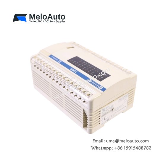


 Analog I/O Module")


WeChat
Scan the QR Code with wechat