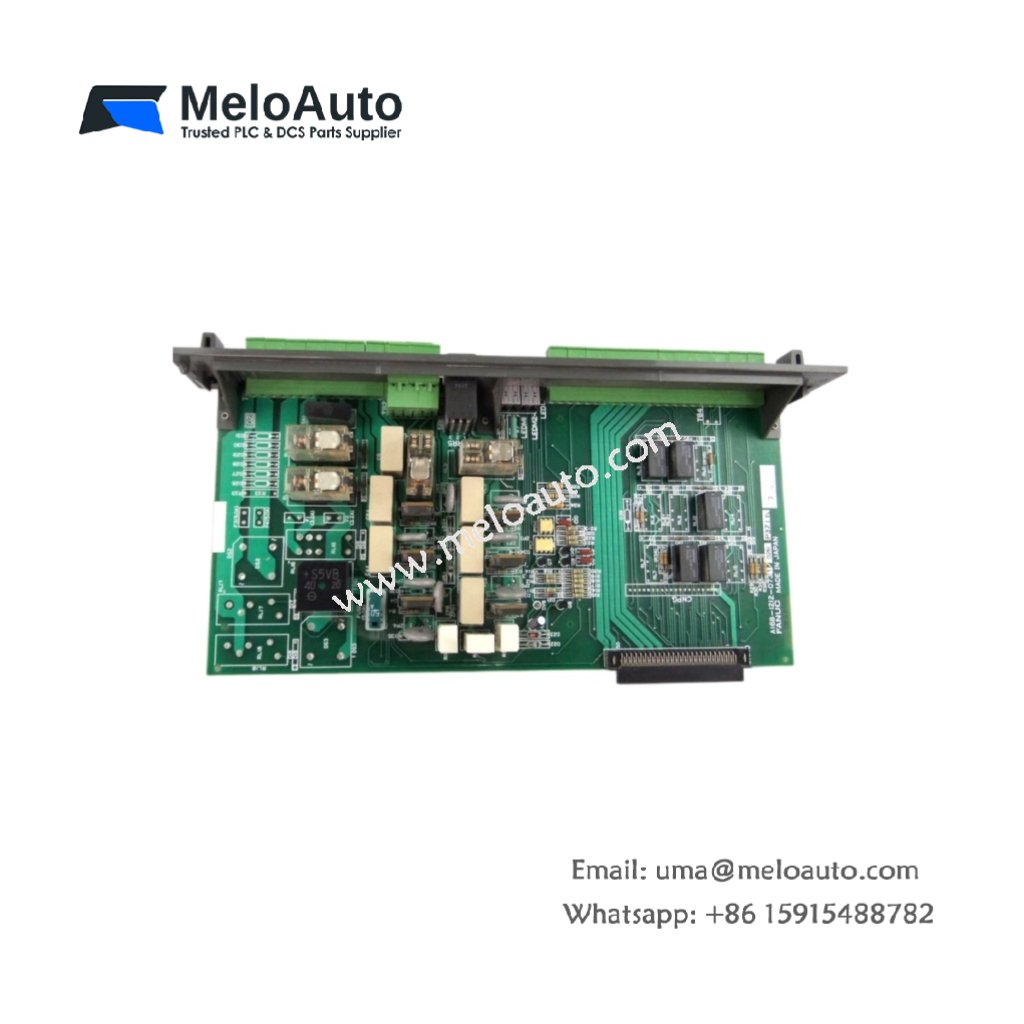

The GE DS200GDPAG1A DS200GDPAG1AJF supplies high-frequency isolated power for IGBT gate drivers. This board converts 125V DC into eight floating 24V outputs. Therefore, it supports larger drive systems with more switching devices.
Product Overview
We built this power supply for high-density applications requiring many isolated channels. Its push-pull topology delivers excellent efficiency across wide load ranges. Moreover, this unit includes output overvoltage clamping for device protection.
Technical Specifications
| Parameter | Specification |
|---|---|
| Dimensions | 24.1 cm (length) x 13.3 cm (width) |
| Weight | 0.61 kg (approximately 1.34 lb) |
| Interface Type | Single 40-pin backplane plus 10-pin output header |
| Component Count | 158 components including dual MOSFETs and toroidal transformer |
| Energy Storage | 4 bulk capacitors (560 µF, 200V) plus 16 ceramic |
| Switching Frequency | 150 kHz fixed with phase-shift control |
| Input Voltage | 125V DC nominal (90V to 150V range) |
| Output Channels | 8 isolated outputs at 24V DC nominal |
| Output Current | 0.5A per channel, 3.0A total maximum |
| Isolation Voltage | 2000V RMS between primary and secondary |
| Efficiency | 89% typical at full load |
| Output Ripple | 80 mV peak-to-peak maximum |
| Hold-up Time | 18 ms at maximum rated load |
Push-Pull Converter Topology
The GE DS200GDPAG1A DS200GDPAG1AJF uses two switching MOSFETs in a push-pull arrangement. Its four bulk capacitors provide energy storage for both primary halves. Additionally, the transformer uses a center-tapped primary for balanced operation. You get high efficiency without the complexity of a full-bridge design.
Energy Storage Configuration
Four bulk capacitors filter the input bus and store energy for hold-up. Sixteen ceramic capacitors provide local decoupling throughout the secondary side. Each output channel has two dedicated ceramic capacitors for noise filtering. These capacitors mount directly across the output terminals for maximum effectiveness. Clean power ensures reliable gate drive for high-power IGBT modules.
Output Channel Features
Each output includes a series Schottky diode for isolation between channels. A zener diode clamps the output voltage to 28V maximum. This clamping protects downstream gate drivers from overvoltage faults. The board does not implement individual channel current limiting. Therefore, add external fuses for each output in critical applications.
Installation Steps
Insert this board into any Mark V slot supporting 40-pin backplane connection. Align the GE DS200GDPAG1A DS200GDPAG1AJF with the card guide slots. Push the board evenly until the backplane connector seats completely. Then secure the front panel with its two captive retaining screws. Connect the output cable to your gate driver distribution board.
Input Voltage Verification
Measure the backplane DC voltage before inserting this power board. The acceptable range spans from 90V to 150V DC. Voltages above 160V will trigger the input overvoltage protection. This protection disables the converter and lights the red fault LED. The board will not restart until you remove the overvoltage condition.
Thermal Performance
The board operates without forced air cooling up to 50°C ambient. Above 50°C, derate the total output power by 4% per degree Celsius. The MOSFETs mount to an internal heatsink for heat spreading. A thermistor monitors the heatsink temperature continuously. The converter shuts down if the heatsink exceeds 95°C. Automatic restart occurs when temperature drops below 80°C.
Application Scope
This high frequency board powers IGBT drivers in large three-phase inverters. It also supplies isolated power for voltage feedback circuits. Many industrial drives use the GE DS200GDPAG1A DS200GDPAG1AJF for main inverter sections. Its eight outputs suit six-pulse rectifiers with brake chopper stages.


, offering high-speed data processing, real-time control, and Ethernet, Modbus, and Profibus support.")


 Analog I/O Module")


WeChat
Scan the QR Code with wechat