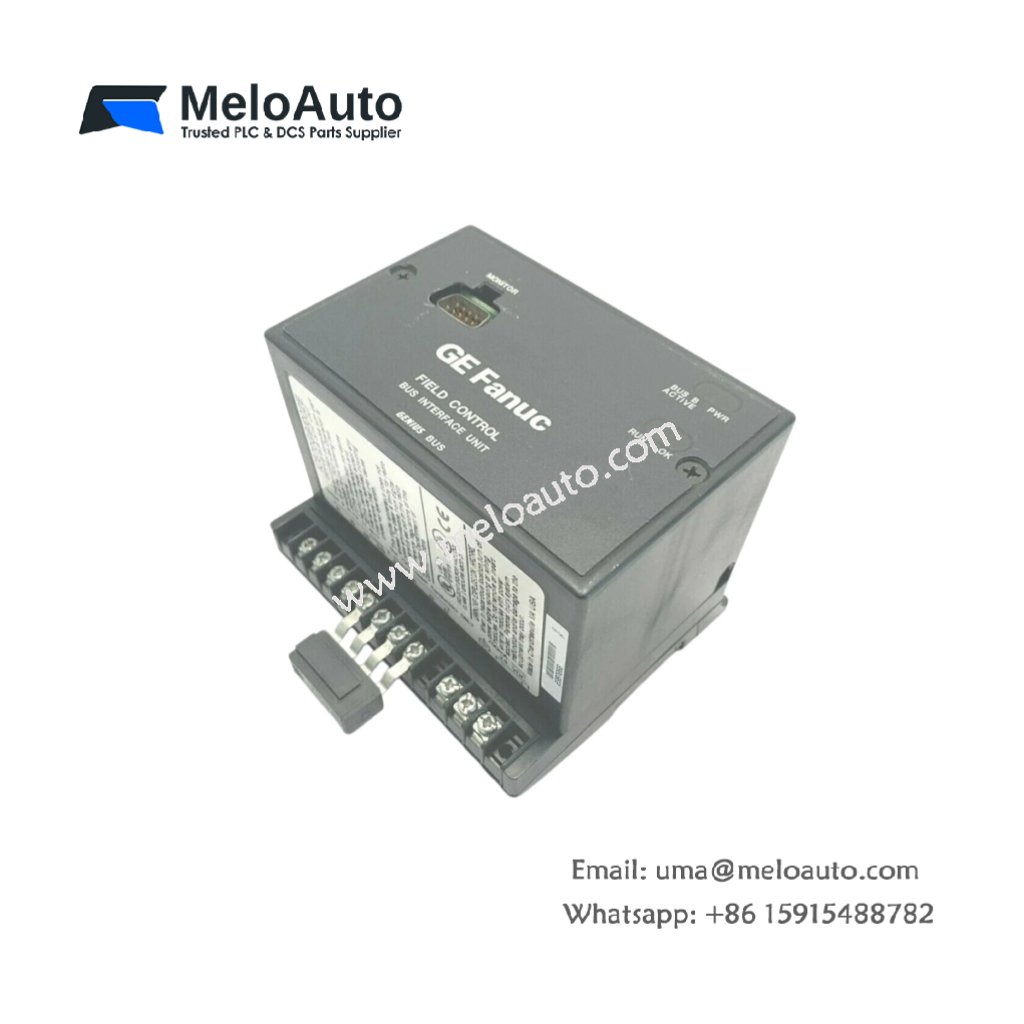
The GE DS200GDPAG1A DS200GDPAG1AGC delivers isolated high-frequency power for IGBT gate drives. This board converts low-voltage DC into multiple floating outputs. Therefore, it enables safe switching of high-power semiconductor devices.
Product Overview
We engineered this power supply with a flyback topology for simplicity and reliability. Its high switching frequency minimizes magnetic component size and weight. Moreover, this unit includes short-circuit protection on every output channel.
Technical Specifications
| Parameter | Specification |
|---|---|
| Dimensions | 24.1 cm (length) x 13.3 cm (width) |
| Weight | 0.56 kg (approximately 1.23 lb) |
| Interface Type | Single 40-pin backplane plus 6-pin output header |
| Component Count | 128 components including switching MOSFET and transformer |
| Energy Storage | 3 bulk capacitors (330 µF, 200V) plus 10 ceramic |
| Switching Frequency | 120 kHz fixed with frequency jittering |
| Input Voltage | 125V DC only (no 250V option) |
| Output Channels | 6 isolated outputs at +15V and -8V bipolar |
| Output Current | 0.5A positive, 0.2A negative per channel |
| Isolation Voltage | 1500V RMS between primary and secondary |
| Efficiency | 85% typical at rated load |
| Protection | Cycle-by-cycle current limiting |
Flyback Converter Topology
The GE DS200GDPAG1A DS200GDPAG1AGC uses a single switching MOSFET for power conversion. Its three bulk capacitors store energy for the flyback transformer primary. Additionally, the controller implements frequency jittering to spread EMI spectrum. You get reduced electromagnetic interference without external filtering components.
Energy Storage Configuration
Three bulk capacitors provide 15 ms of hold-up time at full load. They maintain output regulation during brief input power interruptions. Ten ceramic capacitors decouple each IC and output rectifier locally. These capacitors also filter switching noise from the output rails.
Each channel provides +15V for gate turn-on and -8V for turn-off. The negative bias ensures reliable IGBT turn-off even with Miller coupling. Floating secondary windings allow connection to any IGBT emitter potential. Therefore, you can drive high-side and low-side devices with one board. The maximum potential difference between channels is 1500V DC.
Installation Steps
Insert this board into any Mark V slot with a 40-pin backplane connector. Align the GE DS200GDPAG1A DS200GDPAG1AGC with the card guide slots. Push the board evenly until the backplane connector seats completely. Then secure the front panel with its two captive screws. Connect the output ribbon cable to the gate driver interface board.
Input Requirements
This version accepts only 125V DC input from the cabinet DC bus. Do not connect 250V DC to this board under any circumstances. Verify the input voltage at the backplane before inserting the board. A 250V input will destroy the switching MOSFET instantly. Use a voltmeter to confirm 125V ±10% on the backplane pins.
Load Regulation
Each output channel can source 0.5A continuously at +15V. The negative -8V rail provides up to 0.2A sink capability. All six channels can operate simultaneously at their rated currents. The board maintains ±5% regulation from zero to full load. Exceeding these limits activates the cycle-by-cycle current limiter. The output voltage will fold back automatically.
Application Scope
This high frequency board powers IGBT gate drivers in three-phase inverters. It also supplies isolated power for current and voltage sensors. Many adjustable speed drives use the GE DS200GDPAG1A DS200GDPAG1AGC for main inverter sections.


 Analog I/O Module")


WeChat
Scan the QR Code with wechat