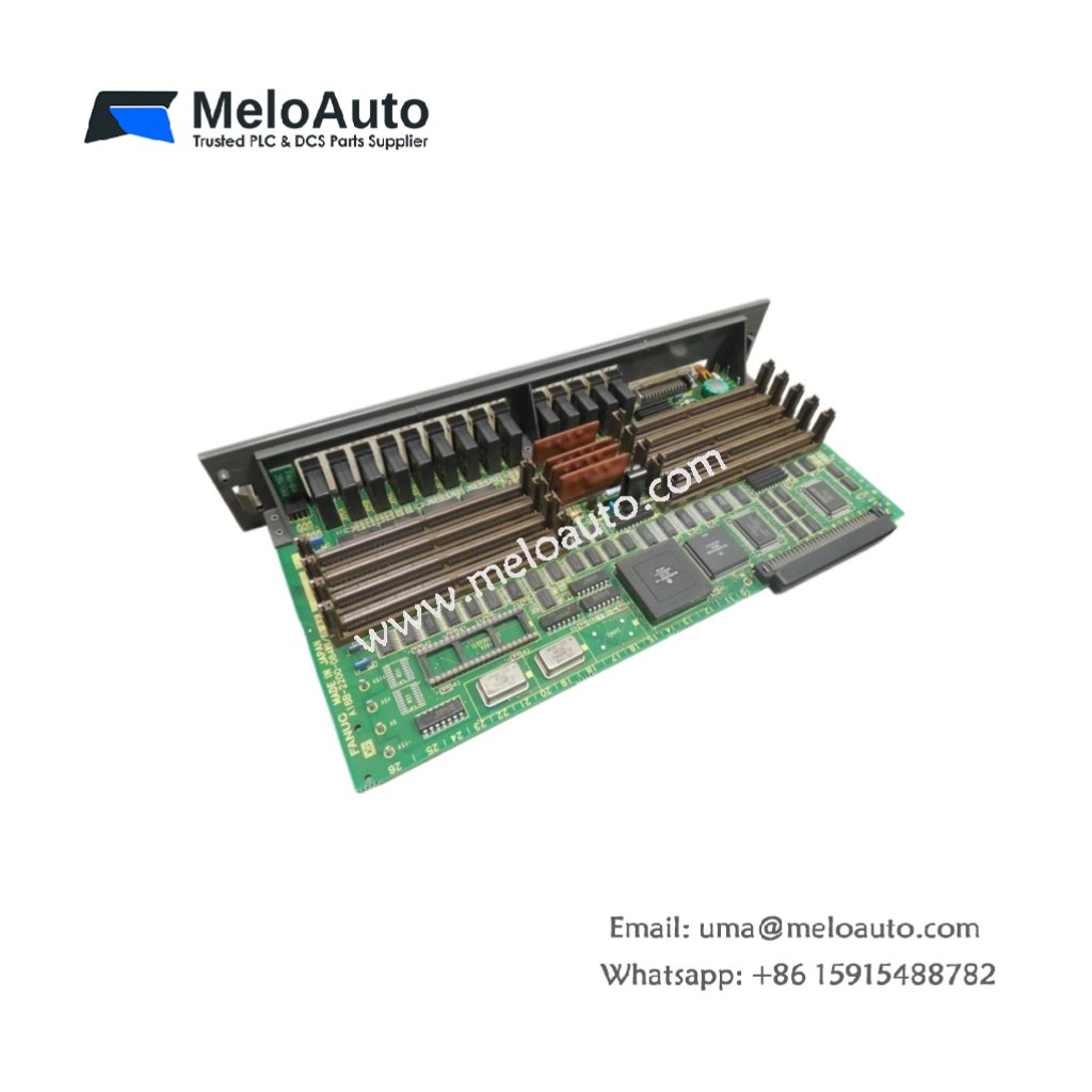
This main PCB board serves as the central backplane for GE CNC controllers. It distributes power and data signals to all connected modules. You can install this board directly into the main CNC rack enclosure. The unit supports axis control, I/O, and communication modules simultaneously.
Technical Specifications & Key Parameters
| Parameter | Detail |
|---|---|
| Product Model | GE A16B-2200-0842 |
| Category | Main PCB Board |
| Dimensions (L x W) | 350 mm x 280 mm |
| Weight | 0.95 kg (2.09 lbs) |
| Layer Construction | 6-layer PCB with dedicated ground and power planes |
| Number of Slots | 8 expansion slots |
| Connector Type | Eight 96-pin DIN 41612 connectors |
| Component Count | 28 capacitors, 36 resistors, 12 bus transceivers, 4 voltage regulators |
| Energy Storage | 4700 µF total capacitance (across multiple rails) |
| Voltage Rails | 5V DC, ±15V DC, 24V DC |
| Maximum Current per Rail | 15 A at 5V DC, 3 A at ±15V DC, 5 A at 24V DC |
| Data Bus Width | 32-bit parallel backplane bus |
| Clock Speed | 25 MHz bus frequency |
| Mounting Holes | Six M4 threaded positions |
| Grounding Points | Two M4 grounding studs |
Detailed Feature Overview
GE A16B-2200-0842 provides eight expansion slots for CNC controller modules. This backplane board connects CPU, axis, and I/O cards through a 32-bit data bus. The 6-layer PCB construction minimizes electrical noise between adjacent slots. Dedicated ground and power planes ensure stable voltage distribution to every module.
Twenty-eight capacitors filter all voltage rails for clean power delivery. Twelve bus transceivers manage data traffic across the backplane efficiently. Four voltage regulators provide local regulation for sensitive logic circuits. The board handles 15 A continuously on the critical 5V DC rail. Consequently, it supports fully loaded racks with high-power modules.
Power Distribution and Signal Integrity
This main board distributes four distinct voltage rails to all eight slots. Each slot receives 5V DC for logic circuits and 24V DC for I/O power. ±15V DC rails support analog servo command signals. The 25 MHz bus clock coordinates data transfers between modules. A 4700 µF capacitor bank stores energy for brief power interruptions. It provides a 15 millisecond hold-up time during dips.
Installation and Physical Requirements
Six M4 mounting holes secure the board to the chassis firmly. Use insulated metal standoffs for proper grounding and vibration resistance. The board weighs 0.95 kg for simple handling during replacement. Two M4 grounding studs connect to the cabinet earth bus bar. Operating temperature ranges from 0°C to 55°C reliably. Keep humidity below 90% without condensation to prevent corrosion. Store the board between -20°C and 70°C for long-term preservation.


 Analog I/O Module")


WeChat
Scan the QR Code with wechat