
Core Function of This Interface Module
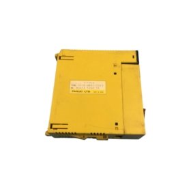
The GE A03B-0807-C012 connects a PLC CPU to external field devices. This interface module buffers and conditions digital signals for reliable communication. It converts between different voltage levels and signal standards. Consequently, the module protects the main controller from electrical noise and transients.
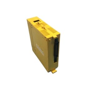
Physical Dimensions and Board Construction
This interface module measures 145 mm in total length. Its width reaches 90 mm for a compact Eurocard form factor. The board thickness stands at 25 mm including all component heights. You will find 178 discrete components on this double-sided PCB. These include optocouplers, line drivers, and transient suppression diodes. The GE A03B-0807-C012 weighs approximately 215 grams for easy installation.
Signal Interface and Channel Configuration
The GE A03B-0807-C012 provides 16 bidirectional signal channels. Each channel operates as either an input or an output. The module automatically detects the signal direction for each pin. Inputs accept 5 V to 24 V DC from field sensors. Outputs deliver 24 V DC at 50 mA for indicator loads. A configuration jumper sets the default power-up state for all outputs.
Voltage Translation and Buffering
This interface module converts TTL-level signals to 24 V DC field voltages. Onboard line drivers boost signal strength for long cable runs. Input circuits include Schmitt triggers for noise immunity. Each channel provides a status LED for immediate visual feedback. The module also includes built-in pull-up or pull-down resistor options. A 4-position DIP switch selects the resistor configuration per group of four channels.
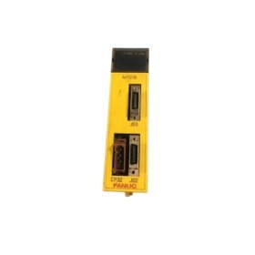
Connector Types and Wiring Details
The GE A03B-0807-C012 uses one 20-pin ribbon cable header for the controller interface. Two 10-pin terminal blocks accept field device wiring for 16 channels. Each terminal accepts wire gauges from 0.2 to 1.5 mm². The board also includes a 4-pin power header for the field supply voltage. Gold-plated contacts ensure reliable connections in industrial environments.
Protection Circuits and Isolation
This interface module provides 1,500 V RMS optical isolation between field and logic. Transient suppression diodes protect each channel from voltage spikes. The module withstands continuous short circuits on all output channels. Reverse polarity protection prevents damage from incorrect field wiring. An onboard fuse protects the field supply input from overload conditions. This fuse is user-replaceable without soldering tools.
Energy Storage and Power Requirements
The GE A03B-0807-C012 draws 90 mA from a 5 V DC logic supply. It also requires 40 mA from a separate 24 V DC field supply at idle. Full output load adds up to 800 mA across 16 channels. The board incorporates four 47 µF electrolytic capacitors for power filtering. Total stored energy reaches approximately 0.04 joules at nominal voltage.
| Parameter | Specification |
|---|---|
| Model | A03B-0807-C012 |
| Brand | GE (General Electric) / Fanuc |
| Category | Interface Module |
| Length x Width | 145 x 90 mm |
| Thickness | 25 mm |
| Weight | 215 grams |
| Component Count | 178 |
| Signal channels | 16 bidirectional |
| Input voltage range | 5 to 24 V DC |
| Output voltage | 24 V DC |
| Output current | 50 mA per channel |
| Output total current | 800 mA maximum |
| Logic supply | 90 mA at 5 V DC |
| Field supply (idle) | 40 mA at 24 V DC |
| Field supply (full load) | 840 mA at 24 V DC |
| Isolation voltage | 1,500 V RMS |
| Configuration DIP switch | 4-position |
| Configuration jumper | 1 (power-up state) |
| Output protection | Short-circuit, reverse polarity |
| Field fuse | User-replaceable |
| Filter capacitors | 4 x 47 µF |
| Total stored energy | 0.04 Joules |
| Control connector | 20-pin ribbon cable |
| Field connectors | 2 x 10-pin terminal block |
| Status LEDs | 16 (one per channel) |
| Wire gauge range | 0.2 to 1.5 mm² |
| Operating temperature | 0°C to +55°C |
Installation and Configuration Notes
You must mount this module in a GE Series 90-30 or Fanuc PLC rack. Always set the DIP switch before installing the module into the rack. Then, verify that the configuration jumper matches your application needs. The module requires no additional software configuration for basic operation. Regular inspection of the field fuse prevents unexpected channel failures over time.


 to pneumatic output (3-15 PSIG) for accurate industrial pressure control.")


 Analog I/O Module")


WeChat
Scan the QR Code with wechat