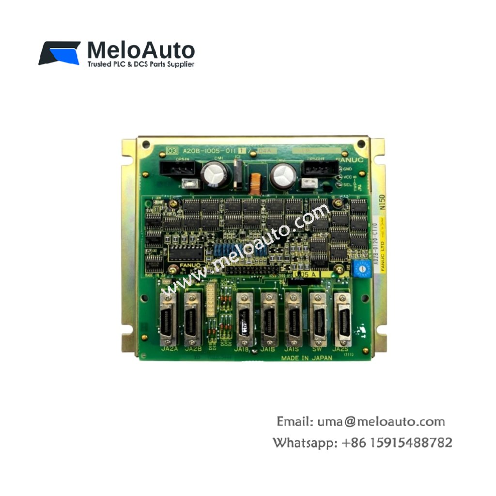
This control board manages input and output signals for CNC power supply units. It monitors voltage levels and triggers protection circuits. You will find this board inside the power supply chassis.
Key Technical Specifications
The A02B-0120-C170 operates as a signal conditioning and monitoring PCB. It converts raw AC voltages into logic-level signals for the main controller. The board also includes overvoltage detection for three separate DC rails.
| Parameter | Technical Data |
|---|---|
| Product Type | Power Supply Control Board |
| Function | Signal conditioning and protection |
| Monitored Rails | +5V, +15V, -15V DC |
| Detection Thresholds | +5V±10%, ±15V±12% |
| Output Signals | 8 x digital status lines |
| Dimensions (L x W) | 22.0 cm x 15.0 cm |
| PCB Layers | 4-layer (FR-4 material) |
| Total Weight | 0.28 kg (0.62 lbs) |
| Main Connector | 1 x 50-pin header |
| Secondary Connectors | 2 x 10-pin headers |
| Onboard Resistors | 62 surface-mount components |
| Onboard Capacitors | 34 ceramic and electrolytic |
| Optocouplers | 4 for output isolation |
| Voltage Comparators | 6 integrated circuits |
| Energy Storage | 150 µF decoupling capacitance |
| Operating Temperature | -10°C to 55°C |
Hardware Architecture and Signal Processing
The A02B-0120-C170 uses six voltage comparators for threshold detection. Sixty-two surface-mount resistors set precise voltage divider ratios. Four optocouplers isolate the eight digital output lines. The board also includes 34 capacitors for noise filtering on all power rails.
Interface and Connectivity
One 50-pin header connects this control board to the main power supply PCB. Two 10-pin headers carry status signals to the CNC controller. The board also features test points for each monitored voltage rail. A 4-pin auxiliary connector supplies +5V logic power from an external source.
Practical Installation Notes
Install this control board inside the power supply unit using four mounting screws. The A02B-0120-C170 requires no separate configuration or jumpers. Always verify correct orientation before inserting the 50-pin cable. Replace the board immediately if you notice any burnt components.


 Analog I/O Module")


WeChat
Scan the QR Code with wechat