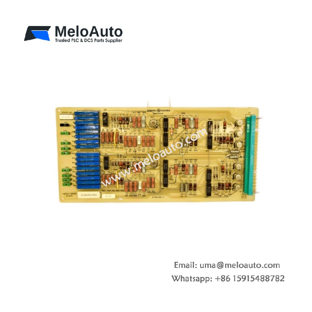
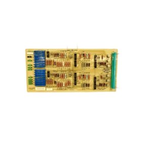
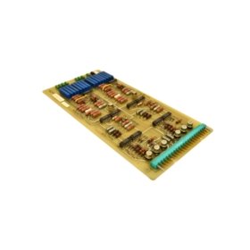
This thrust wear board monitors axial position shifts in turbine rotating assemblies. It measures bearing wear and prevents catastrophic metal-to-metal contact. You will find this board in GE turbine control systems for power generation.
Key Technical Specifications
| Parameter | Details |
|---|---|
| Model Number | 4136J63-G01 |
| Brand | GE (General Electric) |
| Category | Thrust Wear Board / Position Monitor |
| Dimensions (W x H x D) | 190 mm x 150 mm x 25 mm |
| Weight | 370 grams |
| Measurement Range | 0 to 2.5 mm axial displacement |
| Onboard Energy Storage | 4 x 330 µF capacitors (1320 µF total) |
| Component Count | 136 discrete components |
| Input Interface | 2-channel differential (LVDT compatible) |
| Output Signal | 0–10V DC analog (linearized) |
| Alarm Output | 2 relay contacts (warning + danger) |
| Frequency Response | DC to 100 Hz |
| Accuracy | ±0.5% of full scale |
Physical Dimensions and Panel Mounting
This thrust wear board measures 190 mm in width and 150 mm in height. Its depth reaches 25 mm for standard cabinet mounting. The unit weighs 370 grams due to the metal shielding enclosure. Four M4 mounting holes secure the board to a backplate vertically.
Internal Circuitry and Energy Storage
One hundred thirty-six components populate this high-precision measurement board. Four 330 µF capacitors form a 1320 µF total energy storage bank. This bank filters power supply noise for sensitive LVDT conditioning circuits. Consequently, the board measures micrometer-level position changes without electrical interference. A precision rectifier converts AC LVDT signals into DC voltage proportional to position.
Input Interface and Sensor Compatibility
The board accepts two independent LVDT sensors for redundancy applications. Each input includes an internal oscillator to excite the LVDT primary coil. A differential amplifier rejects common-mode noise on long cable runs. You can connect shielded twisted-pair wiring up to 100 meters away. Therefore, the board monitors thrust bearings located deep inside turbine casings.
Output Signals and Alarm Functions
A 0–10V DC analog output provides real-time position readings to a DCS. Two independent relay outputs trigger at programmable warning and danger thresholds. The warning relay activates at 1.5 mm of axial wear. The danger relay triggers at 2.0 mm for immediate turbine shutdown. Green LEDs indicate normal operation, while red LEDs show alarm conditions clearly.


 Analog I/O Module")


WeChat
Scan the QR Code with wechat