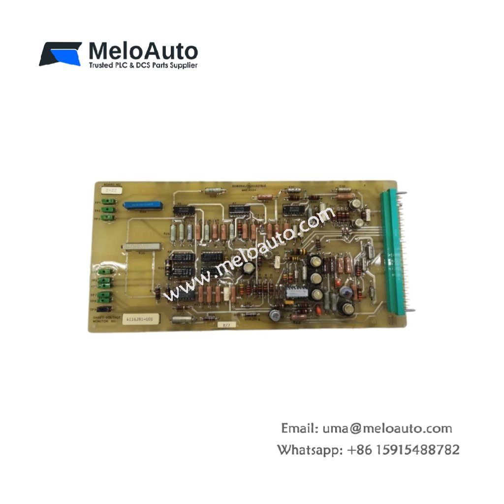
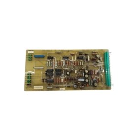
This shaft voltage monitor board detects dangerous voltage buildup on rotating turbine shafts. It protects bearing surfaces from electrical discharge damage. You will find this board in GE turbine control systems for power generation plants.
Key Technical Specifications
| Parameter | Details |
|---|---|
| Model Number | 4116J81-G01 |
| Brand | GE (General Electric) |
| Category | Shaft Voltage Monitor Board / Protection PCB |
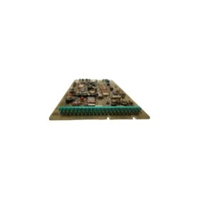
| Dimensions (W x H x D) | 180 mm x 140 mm x 25 mm |
| Weight | 350 grams |
| Measurement Range | 0 to 50V AC peak-to-peak |
| Onboard Energy Storage | 4 x 220 µF capacitors (880 µF total) |
| Component Count | 124 discrete components |
| Input Interface | 2-terminal high-impedance differential |
| Output Signal | 0–10V DC analog (scaled) |
| Alarm Output | Relay contact (NO/NC, 1A at 24V DC) |
| Frequency Response | 50 Hz to 10 kHz |
Physical Dimensions and Panel Mounting
This monitor board measures 180 mm in width and 140 mm in height. Its depth reaches 25 mm for standard control cabinet mounting. The unit weighs 350 grams due to the metal shielding enclosure. Four M4 mounting holes secure the board to a backplate vertically.
Internal Circuitry and Energy Storage
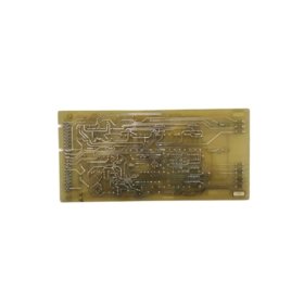
One hundred twenty-four components populate this high-impedance measurement board. Four 220 µF capacitors form an 880 µF total energy storage bank. This bank filters power supply noise for sensitive analog front-end circuits. Consequently, the board measures microvolt-level signals accurately without interference. A differential amplifier rejects common-mode noise up to 100V.
Measurement Principle and Input Interface
The board measures AC voltage between the turbine shaft and ground. A high-impedance input (10 MΩ) draws virtually no current from the shaft. Two terminal blocks accept shielded twisted-pair wiring for noise reduction. The monitor processes frequencies from 50 Hz up to 10 kHz. Therefore, it captures both fundamental and harmonic shaft voltage components.
Output Signals and Alarm Functions
A 0–10V DC analog output provides real-time voltage readings to a DCS. An adjustable threshold triggers a relay when voltage exceeds safe limits. The relay contacts can shut down the turbine or sound an alarm. Green and red LEDs indicate normal operation or fault conditions respectively. You can also route the analog signal to a chart recorder for trend analysis.


 Analog I/O Module")


WeChat
Scan the QR Code with wechat