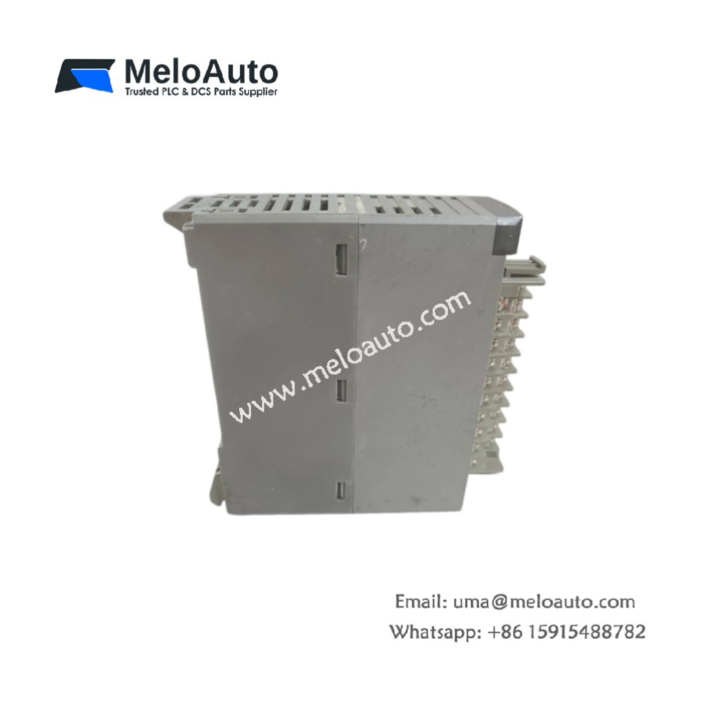
This digital I/O module provides mixed input and output capability for FUJI MICREX-SX automation systems. It interfaces directly with field sensors and actuators for machine control. Therefore, it enables reliable industrial automation for manufacturing applications.
Physical and I/O Specifications
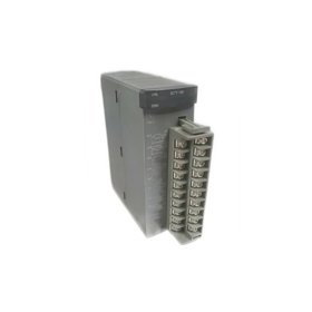
The FUJI NP1W1606U measures 13.0 cm in length and 9.5 cm in width. Moreover, its module weight equals approximately 0.32 kg for DIN rail mounting. A single 24-pin removable terminal block handles all field wiring connections. Additionally, this module contains sixteen input channels and six output channels.
| Parameter | Specification |
|---|---|
| Brand | FUJI Electric |
| Full Model | NP1W1606U |
| Category | Digital Input/Output Module |
| Dimensions (L x W x H) | 13.0 cm x 9.5 cm x 6.0 cm (5.12″ x 3.74″ x 2.36″) |
| Module Weight | 0.32 kg (0.71 lbs) |
| Primary Interface | 1 x 24-pin Removable Screw Terminal Block |
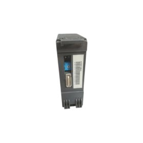
| Backplane Interface | 1 x 48-pin Male Connector (MICREX-SX Rack) |
| Operating Voltage | 24 VDC from Backplane (19.2 to 28.8 VDC) |
| Power Consumption | 3.5 W (Typical) |
| Digital Input Channels | 16 Channels (24 VDC, Sink/Source) |
| Input Voltage Range | 0 to 30 VDC |
| Input On-State Voltage | > 15 VDC |
| Input Off-State Voltage | < 5 VDC |
| Input Impedance | 4.7 kΩ |
| Input Response Time | 4 ms (Typical) |
| Input Isolation | Optocoupler (1500 Vrms) |
| Digital Output Channels | 6 Channels (Transistor, NPN Sinking) |
| Output Voltage Range | 12 to 24 VDC |
| Output Current per Channel | 1.0 A (Continuous), 1.5 A (Peak) |
| Total Output Current | 4.0 A Maximum (All Channels Combined) |
| Output On-State Drop | < 1.2 VDC at 1.0 A |
| Output Off-State Leakage | < 0.1 mA at 24 VDC |
| Output Protection | Short Circuit + Overtemperature |
| Output Response Time | 0.5 ms Maximum |
| On-Board Components | 16 Input Optocouplers + 6 Output Transistors + 6 Flyback Diodes + 1 Microcontroller + 2 Current Sense ICs + 6 Protection Diodes + 1 Voltage Regulator + 1 Fuse |
| Energy Storage | 3 x 220 µF Electrolytic Capacitors (35V) + 2 x 47 µF Tantalum (25V) |
| Isolation Rating | 1500 Vrms (Field to Logic) |
| Operating Temperature | 0°C to +55°C (32°F to 131°F) |
| Storage Temperature | -25°C to +85°C (-13°F to 185°F) |
| Mounting Type | DIN Rail or MICREX-SX PLC Rack |
| Status Indicators | 16 Green LEDs (Inputs) + 6 Green LEDs (Outputs) + 1 Green LED (Power) + 1 Red LED (Fault) + 1 Green LED (24V OK) |
Input Channel Features and Signal Processing
The FUJI NP1W1606U accepts sixteen discrete input signals at 24 VDC from field sensors. Specifically, each input includes an optocoupler for complete electrical isolation. In addition, the input impedance of 4.7 kΩ suits standard industrial proximity switches. Moreover, all input channels respond within 4 milliseconds to signal changes. Consequently, this module captures field events reliably for machine control.
Output Channel Features and Protection Systems
Six transistor outputs provide NPN sinking capability for actuator control. For instance, each output delivers 1.0 amp continuously at 24 VDC. In addition, internal flyback diodes protect the transistors when driving inductive loads. Furthermore, short circuit protection shuts down any faulty channel automatically. Moreover, the higher current rating suits small motors and solenoids directly. Thus, this module survives wiring mistakes without permanent damage.
Energy Storage and Operational Stability
This digital I/O module stores energy using five onboard capacitors for power filtering. Specifically, three electrolytic capacitors smooth the 24 VDC supply for stable operation. In addition, two tantalum capacitors provide high-frequency noise suppression for logic circuits. Furthermore, these capacitors maintain I/O status during brief power interruptions. Therefore, the FUJI NP1W1606U continues operating through minor supply dips reliably.
Installation and Diagnostic Indicators
Twenty-five LED indicators provide operational status at a glance on this module. First, sixteen green LEDs light when each corresponding input receives an active signal. Second, six green LEDs illuminate when each output channel turns on. Third, a green Power LED indicates the presence of backplane operating voltage. Fourth, a green 24V OK LED shows external load supply voltage is present. Finally, a red Fault LED signals overtemperature or overcurrent conditions. Thus, you can diagnose system status instantly without external tools.


 is a 64-channel low-level analog input multiplexer for industrial automation, featuring fast data acquisition and high reliability.")

 Analog I/O Module")


WeChat
Scan the QR Code with wechat