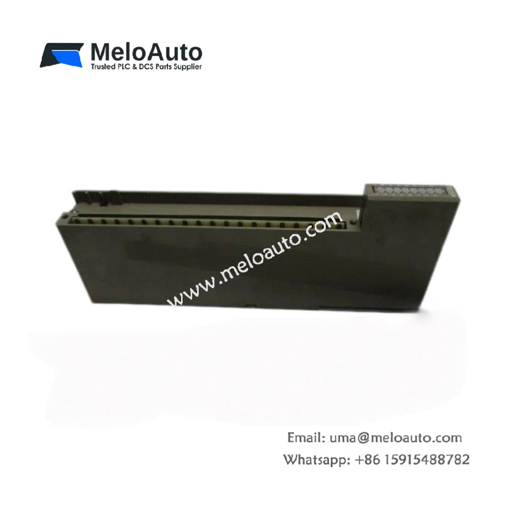
The Fuji FTU210B provides ten discrete output channels for load control. This module drives solenoids, contactors, and indicator lamps reliably. It connects seamlessly to FTU series PLC systems. Maintenance teams value this unit for its simple troubleshooting features.
Complete Technical Specifications
| Parameter | Specification |
|---|---|
| Dimensions (W x H x D) | 145 mm x 90 mm x 55 mm |
| Weight | 0.35 kg |
| Number of Output Points | 10 channels |
| Output Type | Relay, Form A (SPST-NO) |
| Output Current per Channel | 2 A at 250V AC / 30V DC |
| Total Output Current | 10 A maximum |
| Contact Material | Silver alloy |
| Mechanical Life | 20 million operations |
| Electrical Life | 100,000 operations at rated load |
| Internal Energy Storage | 330 µF capacitor |
| Operating Voltage | 24V DC ±20% |
| Power Consumption | 3 W typical |
| Response Time | 10 ms maximum |
Physical Layout and Connection Design
The Fuji FTU210B weighs 0.35 kilograms for standard panel mounting. Its 145 mm width holds ten independent relay channels. Each output includes a yellow status LED for visual confirmation. A 20‑pin terminal block accepts up to 2.5 mm² wires. The module uses replaceable relays for extended service life. An internal 330 µF capacitor smooths supply voltage variations.
Output Characteristics and Switching Performance
Each relay channel handles 2 amperes continuously at 250V AC. The contacts also switch 2 amperes at 30V DC. Therefore, this module controls small motors and heating elements directly. The mechanical life reaches 20 million switching cycles. However, electrical life drops to 100,000 cycles under full load. The response time stays within 10 milliseconds for most applications.
Installation and Wiring Guidelines
Mount the Fuji FTU210B on a DIN rail or using M4 screws. First, disconnect all power sources before wiring. Then connect the 24V DC supply to the power terminals. Wire each load between the common and NO contact. Use appropriate fuses for each output channel. After wiring, apply power and test each relay individually. Always suppress inductive loads with diode or RC snubbers.
System Integration and Application Notes
This output module works with FTU series PLC CPUs. It occupies one position in the module rack. Typical applications include conveyor motor starters and valve actuators. The unit also suits alarm annunciators and pilot lights. For AC loads, connect the common terminal to the phase line. For DC loads, connect common to the positive supply rail.


, baud rates to 115.2k")


 Analog I/O Module")


WeChat
Scan the QR Code with wechat