The Fuji NP1X1610-R1/RI accepts sixteen discrete 24V DC signals. This module connects field sensors directly to the NP1 series backplane. It filters electrical noise for reliable signal acquisition. Many control engineers choose this unit for high‑density input applications.
Complete Technical Specifications
| Parameter | Specification |
|---|---|
| Dimensions (W x H x D) | 68 mm x 110 mm x 85 mm |
| Weight | 0.28 kg |
| Number of Input Points | 16 channels |
| Input Type | 24V DC sink/source |
| Input Voltage Range | 10–30V DC |
| Input Current per Channel | 7 mA typical |
| ON Voltage Threshold | ≥15V DC |
| OFF Voltage Threshold | ≤5V DC |
| Response Time (ON to OFF) | 1.5 ms maximum |
| Response Time (OFF to ON) | 1.5 ms maximum |
| Internal Energy Storage | 220 µF capacitor |
| Isolation Method | Optocoupler per channel |
| Power Consumption | 2 W typical |
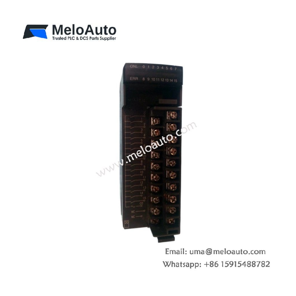
Physical Layout and Connection Details
The Fuji NP1X1610-R1/RI weighs only 0.28 kilograms for lightweight mounting. Its 68 mm width occupies a single slot on the base board. Sixteen input channels appear on two 20‑pin terminal blocks. Each channel includes a red status LED for visual indication. A 220 µF capacitor filters supply voltage fluctuations. The module uses optocouplers to isolate each input from the backplane.
Input Characteristics and Signal Processing
Each channel accepts voltages from 10V up to 30V DC. The module recognizes any signal above 15V as logic high. Similarly, signals below 5V register as logic low. The response time reaches just 1.5 milliseconds for both transitions. Therefore, this unit captures fast sensor pulses without missing events. The 7 mA input current suits most proximity switches and push buttons.
Installation and Wiring Guidelines
Mount the Fuji NP1X1610-R1/RI into any NP1 base board slot. First, disconnect system power completely before handling. Then connect each sensor wire to the designated terminal. Use a common 24V source for all sink/source configurations. The module accepts both NPN and PNP sensor types. After wiring, apply power and verify each LED lights correctly. Finally, test every channel with a signal generator.
System Integration and Application Notes
This input module works with all NP1 series CPUs and power supplies. It occupies one slot regardless of channel count. Typical applications include limit switch monitoring and encoder feedback. The unit also suits photoelectric sensor arrays on packaging lines. For expanding beyond 16 points, add a second module. The compact design allows dense cabinet layouts.


 Analog I/O Module")


WeChat
Scan the QR Code with wechat