 MeloAuto-Trusted PLC & DCS Parts Supplier
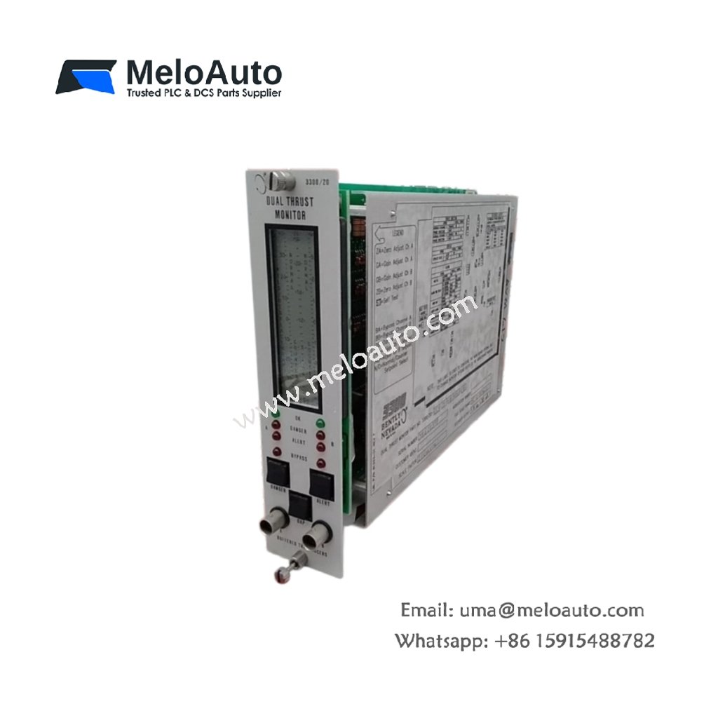
3300 Series Two-Channel Thrust Position Monitor
The 3300/20-13-03-01-00-00 provides continuous thrust position monitoring for two independent transducer inputs. This module measures axial shaft displacement in rotating machinery like turbines and compressors. It processes each proximity probe signal and compares it against configurable alarm thresholds. The device then activates the appropriate relay outputs when any channel exceeds its setpoint.
Key Technical Specifications
| Parameter | Specification |
|---|---|
| Model | 3300/20-13-03-01-00-00 |
| Series | 3300 Series |
| Function | Dual-channel thrust position monitor |
| Input Type | Accepts two proximity probe signals |
| Power Supply | Requires +24 Vdc at 180 mA nominal |
| Output Relays | Includes two alarm relays and one danger relay |
| Measurement Range | Spans from -24 Vdc to 0 Vdc input |
| Frequency Response | Covers a range from DC to 10.0 kHz |
| Input Impedance | Provides 100 kΩ impedance per channel |
| Alarm Setpoints | Individually configurable per channel |
| Time Delay | Adjustable from 0.1 to 10.0 seconds |
| Operating Temperature | Functions from -20°C to +65°C |
| Storage Temperature | Withstands -40°C to +85°C |
| Dimensions | Measures 241.3 mm x 25.4 mm x 152.4 mm |
| Weight | Weighs approximately 1.3 kg |
| Mounting | Fits standard 19-inch rack enclosures |
| Termination | Uses pluggable screw terminal blocks |
| LED Indicators | Displays OK, ALERT, and DANGER per channel |
Thrust Position Monitoring and Protection
This monitor continuously evaluates each proximity probe signal for axial displacement. It then triggers the alarm relay when a channel reaches the first threshold. Subsequently, the danger relay activates if the displacement reaches the critical limit. Each channel operates independently, so a fault on one does not affect the other. The device also supplies a buffered output for external monitoring systems.
Installation and Configuration
Mount the 3300/20-13-03-01-00-00 securely into an available rack slot first. Next, connect the proximity probe cables to the designated input terminals. After that, apply +24 Vdc power and verify the OK LED illuminates. You can then adjust the alarm setpoints using the front-panel potentiometers. Finally, set the time delay to prevent false trips during transient conditions.
Maintenance and Operational Reliability
This module retains all configuration parameters in non-volatile memory. Therefore, you will not lose your calibration values after a power cycle. We recommend you perform periodic verification of both input channels. You should also inspect the terminal connections for any signs of loosening or corrosion.




WeChat
Scan the QR Code with wechat